-
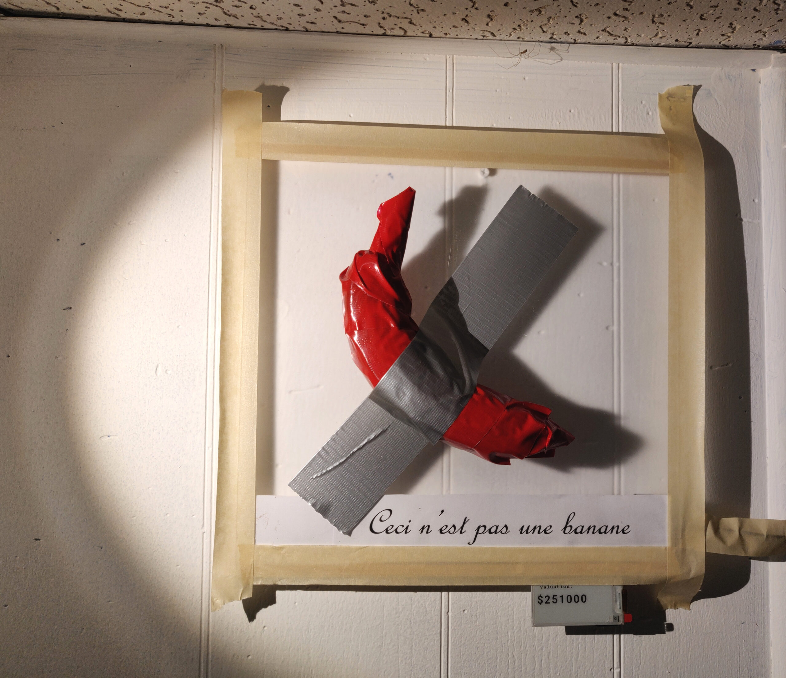
Protect Your Banana! (Duct taped to a wall)
Ah, the United States Supreme Court. Wrestling with the country’s thorniest legal questions of bodily autonomy, presidential immunity and whether you can ducttape a banana to a (consenting) wall. No, seriously, the Supreme Court issued an 80-page ruling on whether taping a banana to a wall is copyrightable (TL;DR: it isn’t). Suppose, just suppose, you
-

Aimee, a short story
–Thursday, March 31, 2039– “That was brilliant!”, Aimee said. “Simple convolutional neural nets they can build and train themselves. They loved it! The look on their faces when you threw the colorful jellybeans in with the Lego bricks just after they finished training their classifiers. And when they realized they could just add another layer
-

Solved: 2014 Mazda 3 Intermittent Liftgate (trunk) Latch, Won’t Open
TL;DR: Software locked it out because front passenger side door latch detects a nonexistent key in its nonexistent keyhole. It ultimately wasn’t, but could have been, dependent on which hand you used to open it! Before I begin – and before anyone pictures me with cape and golden locks blowing in a heroic breeze –
-

Got a health survey call from BRFSS?
TL;DR: Noping out of a probably-not-a-scam scientific study that should benefit everyone, with the ongoing realization that I can’t currently trust the fucking CDC not to do me or my family harm instead of good in the current administration. Takeaways: I try not to get into overtly political topics here, but there’s no dancing around
-

Silly Sideprojects: The Lighting-Up-Crotch Snowman!
Finally, a blinky project of the scale I can actually bite off these days (unlike pre-kids), but it requires a bit of backstory. My wife’s mom absolutely loves Christmas, and like many families, their Christmas is full of tradition. It just wouldn’t be Christmas without egg dish, Dead Thelma Neuboldt’s Merry Christmas Chicken in the
-

Electric Monks: AI User Agents and Agency in the AIPocalypse
I’ll begin this rant with a tiny bit of history: look at the HTTP(S) headers a modern Web browser sends with its requests, and you’ll notice that for historical reasons it refers to itself by an odd name: not a browser, not a program, not an App, but a user-agent. While the term may have
-

Clippy, just trying to be helpful!
Louis Rossmann, my spirit animal from the alternate reality where I don’t have a day job and kids, is again speaking some truths. He makes a great argument that we should be pining nostalgic for Clippy, the dancing paperclip everyone of a certain vintage hated for being naively helpful, as opposed to hating our industry
-
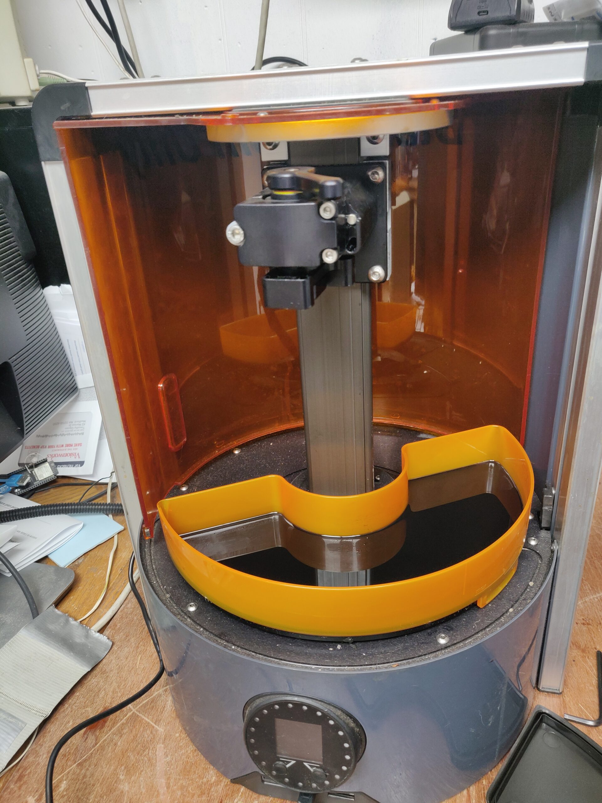
Autodesk Ember SLA (Resin) 3D Printer – Findings, Document Dump and new Slicer!
Or: Tim reverse-engineers an open-source product to reconstruct the open-source materials! Long story short, I picked up this Autodesk “open-source” (words I thought I would never hear together) stereolithography printer at a local freecycle event. I thought it was a vacuum cleaner until I saw the Autodesk name on the back label. On realizing what
-
Kalmbach Media / Discover Magazine Subscription Scam
Hello friends from the search engines! If you’re reading this, you’re not the only one to receive one. With apologies in advance for turning this blog into an archive of my snail-mail, here is an “invoice” I got the other day, for a magazine I used to have a gift subscription to years-and-years ago. As
-
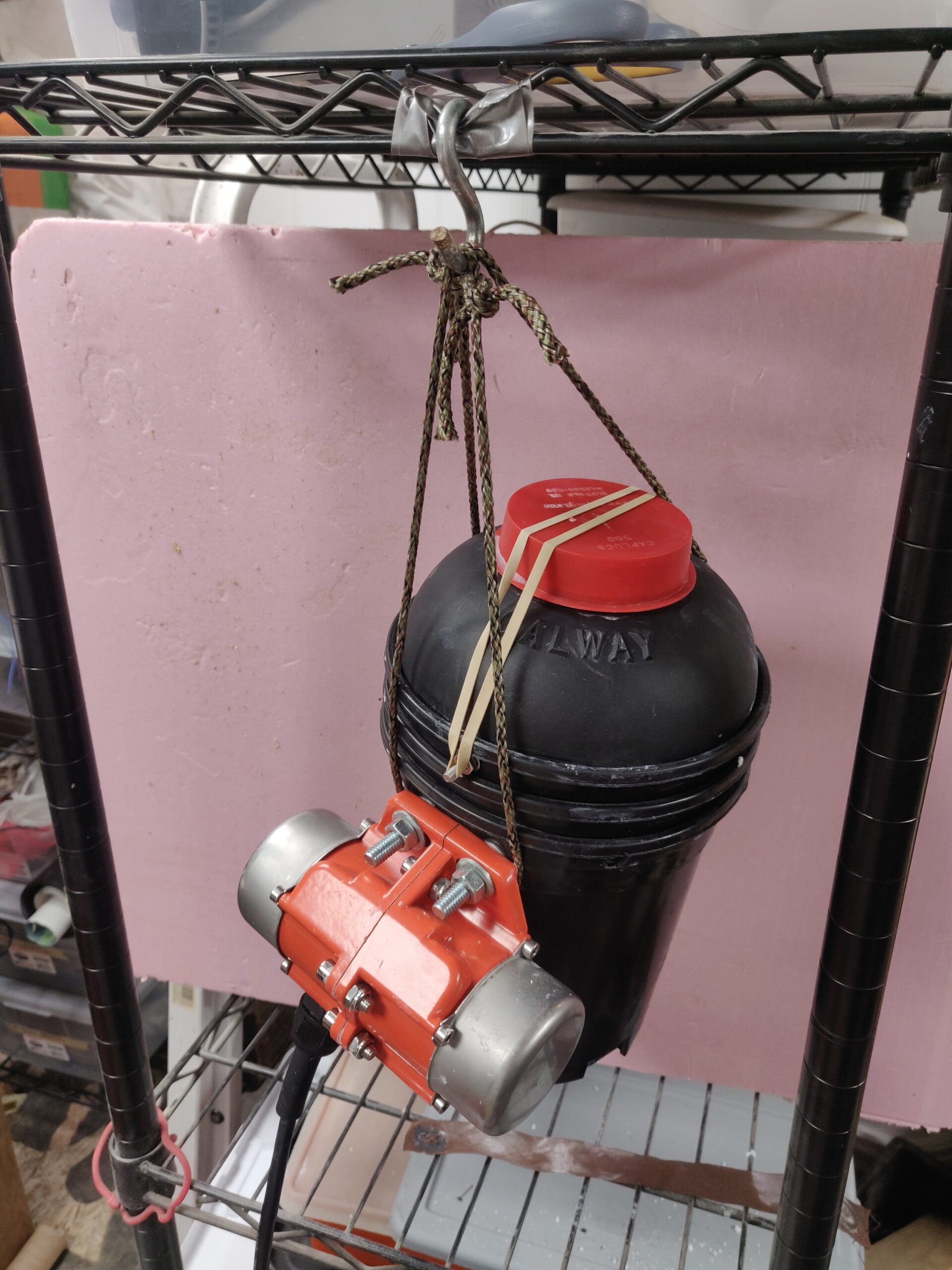
Build a Minimalist DIY Vibratory Rock Tumbler
My son and I have gotten into rock tumbling a bit, so I put a small vibratory tumbler on my “would be nice” holiday wishlist. So, apparently this hobby has gotten popular lately and these things can’t be had for love or money. Maybe for lots of money, but I wasn’t ready to drop 400
-

Enshittification, the honeymoon phase and the Great Throttle Map Conspiracy
By now, you have probably heard a thing or two about enshittification – the process by which online platforms lure a customer base with favorable terms, then gradually sour the deal once users are locked in. Often, this involves a multilevel game of “the customer is the product”, or as Cory Doctorow puts it: This
-
KoolStone Rock Tumbler Replacement Belt sourcing
A very quick note to my future self: AFAICT the KoolStone (iKoolStone?) belts are plain rubber O-rings, which come in standardized size numbers. For the KoolStone (C1? 2.5lb capacity) rock tumbler, it is size 231 (approximately 2-5/8″ ID, 2-7/8″ OD, 1/8″ width). Durometer unknown, but 50A durometer seems to be working well. These can be
-
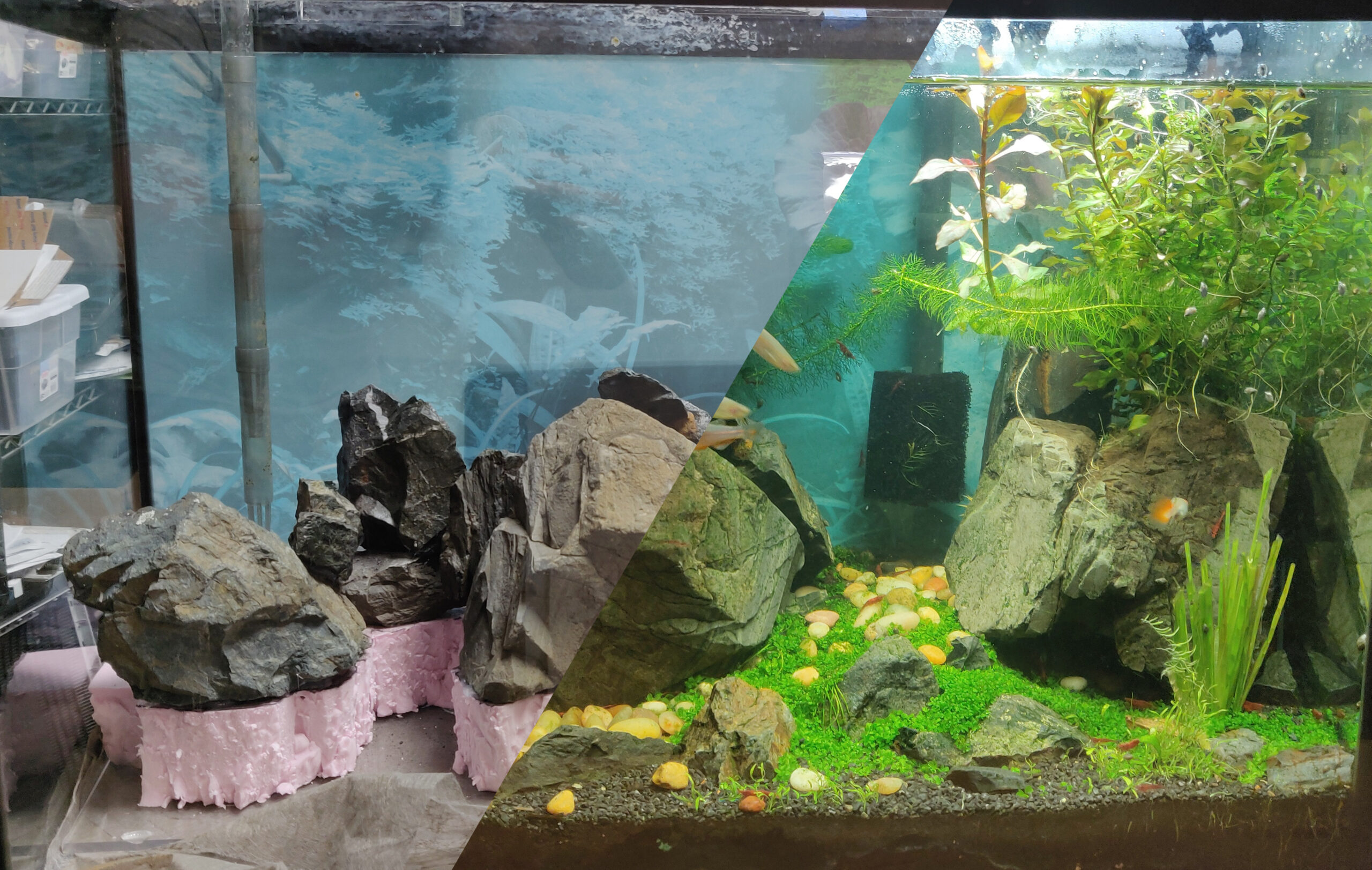
Pandemic Project: Aquascaping with Insulating Foam & Found Objects
“The pandemic is over!”, says the world, as I sit here cooped up in a household full of COVID and no childcare :p Anyway, a bit late writing this up, but when the actual COVID lockdowns were going strong and everyone needed hobbies, I decided to put together a nice fishtank aquascape using mostly stuff
-

Notes To Myself: Remote Couch Gaming with RPI5 / Moonlight
Hey Future Tim, in case you ever need to set it up again, here is a guide to setting up game streaming from a beefy desktop PC (game host / backend) to a Raspberry Pi 5 (game display client / frontend) with low latency, both for the input devices (keyboard/mouse or controllers linked to the
-
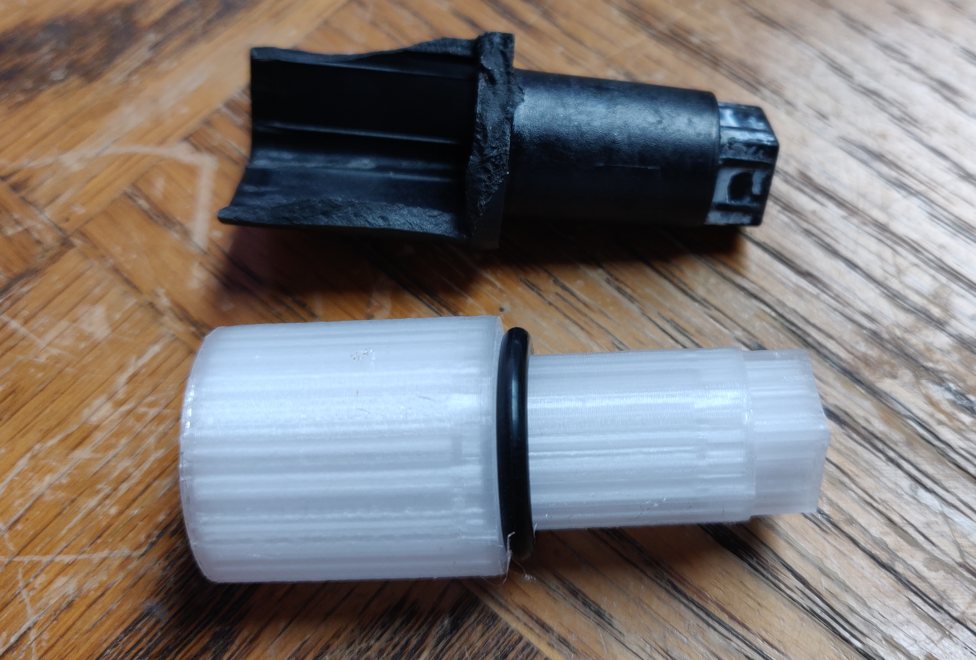
3D-Printable replacement plastic coupler bit (stem driver) for Kohler Rite-Temp(R) shower faucet handles
Go for a shower, and the new (professionally installed just over 1 year ago) Kohler shower faucet handle just spins in a full circle with some rough detents without any water coming out. After figuring out what the actual product is and how to extract it from the wall (nary a screw or screw-hiding cover
-
Exactly how much work is a half-assed job?
If you tend to work smarter, not harder, you may at some point in your life have been accused of doing a half-assed job. But what, exactly, does that mean? How much work are you doing? How much energy are you putting into it?
-
Not enough ass in your pants?
Growing up, when someone was attempting a job that was clearly too big for them, my uncle would say: “You don’t have enough ass in your pants for that!” What this expression meant of course was that all the strength, gumption or determination in the world were irrelevant, and the task at hand just required
-

Solved: Control Raspberry Pi media center (Kodi) with Roku TV’s remote over HDMI CEC
TL;DR if you already figured out the documented stuff: Enable 2-way CEC (keypresses from TV remote to attached device) in the Roku secret menu: Quickly (within ~ 5 seconds) press Home 5 times, rewind, down, fast forward, down, rewind, and “Enable CEC Remote Control”. A further update: After doing all this, I found Kodi on
-
MAPFRE Data Breach, or, “What’s a MAPFRE and why do they have my information?”
So, I had this brilliant idea for a legitimate passive income opportunity: Start a company with an online presence and terrible information security. Buy personal information in bulk, store copies of it on our servers, then sit back as eeevil hackers steal it. Repeatedly. Each time it happens, offer the affected customers 12 months of
-

Spookifying Haunted Mirror build using Stable Diffusion
For this Halloween, I built this haunted mirror display for the porch that turns any trick-or-treaters extra spooky. Using the voodoo power of AI, those who gaze into the mirror will be treated to a visage of their best Halloween self. See below for code and build tips if you’re interested in making your own!
Find stuff…
Pages
- Das Blinkenlichten – wearable lighting
- Goldmine Electronics LCD pinout (mini-teardown)
- Mosquino: an Arduino-based energy harvesting development board
- Pick and Place Project
Categories
Tags
3dprinting ai blinkenlichten broken brokenbydesign circuit bending cnc codebending comcast corporates crashes dell error evil foodz gadget garden glitch music groan humor idiocy led lirc machine meme NES norrisolide pickplace precision python recipe reprap rgb salesdouche serial stupidity sucks t3400 teardown ticket timtearsitapart usb webcam windows xp