So, I found this lovely behemoth in my work’s e-waste pile and yanked it out, figuring on harvesting a nice big diffuser and backlight for a different project. But a quick search on the partnumber showed this thing is pretty impressively specced, and maybe I’d rather have a go at getting it running again instead. Plus, after many moons of mostly shuffling paper and “FTEs” (the exciting new term for humans who actually do work), it would be an excuse to actually get my hands dirty with actual electronics again!
it turns out all it needed was a little love. That and a new motherboard. Yes, in the end I took the easy way out (I know you were expecting a valiant tale of BGA reballing or fabricating my own rectifier diodes from corroded razor blades), but maybe some of the information below might be helpful to someone in a similar boat. Even if it’s as simple as lifting the back off and swapping boards, a handful of quick tests might help you determine which board needs replacing. As of this writing, replacement boards run ~$60-$100USD, so not a bad deal. Plus, you can generate a bit less landfill fodder!
A couple TL;DR troubleshooting tips:
- Only the power supply and interface board (mainboard) (and obviously, front-panel button/LED board) are needed to show basic “signs of life” in response to the power button. Everything else, including the LCD panel (T-Con board), backlight board and even that silly card-reader daughterboard, can be detached without affecting basic operation.
- This means if the unit doesn’t power on, it’s pretty much either the power supply or interface board.
- Likewise, the backlight board and card reader board can be failed/disconnected and you should still get video if the mainboard and power supply are working. Obviously, the LCD panel (T-Con board) must be connected to check video output, and without a working backlight you’ll need to shine a good flashlight into the front of the LCD at point-blank range to see if it’s doing anything. Without a video input, a “No input source” type dialog will bounce slowly around the screen for a couple minutes.
- Basic life/bootup signs from the interface board (lights, serial output, detection by the PC) are not a guarantee that the interface board is in good working order.
Assessing The Patient
Having never seen this monitor actually running before, I wasn’t sure what to expect. Is there a power LED? Should anything light up automatically when plugged in? Should something happen if you press the power switch, even if there is no video source? Should the little unmarked whitish nubbins (menu buttons) on the side near the power switch visibly do anything when pressed?
What’s supposed to happen is when plugged in, the little white nubbins light up white with a brief animation pattern (or at minimum, do so if you press the power button, which also lights up). Anyway, this unit did none of these things. Despite various fiddling with the nubbins, power button, plugging in video sources, etc., there were no visible signs of life. So lets get inside!
Actually opening the unit is a bit of a trick; there are almost no visible screws and the whole thing just snaps together. The actual, official way to open this product is to wedge some plastic spudgers (and probably a couple kitchen knives after you run out of spudgers) into the seam between the front bezel and back panel, and start prying the two apart until it feels like you’re going to break something. Alternately, as shown in this iFixit guide, try pulling at the bezel where it contacts the LCD. Eventually, the front bezel can be detached and carefully flipped out of the way (but not very far; it’s still tethered by a pair of non-removable ribbon cables to the power/menu button assembly on the bezel, which is plastic-welded in place and hidden behind a sticker of sorts). At this point you can either be very delicate with it until you can get the rest of the innards out and get to the removable side of the ribbon, or do what I did and just snap the button board off from the little plastic welds, then tape/glue it back in place at the end. This assembly is actually two boards, the plastic-welded menu buttons and a physical power button board, which is held on with two small screws.
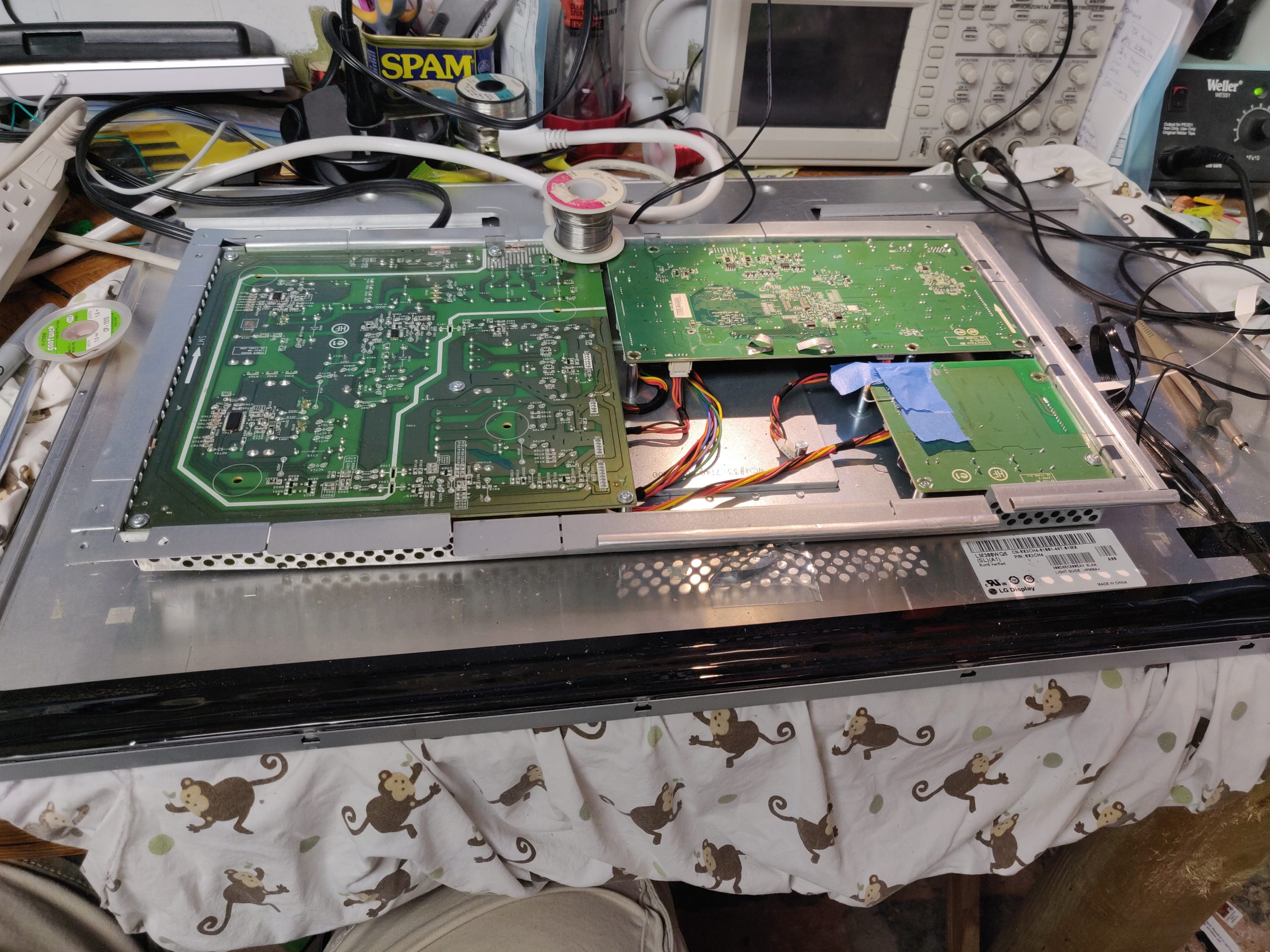
Either way, with the bezel removed, you can place the unit screen-side-down (on a soft, non-marring surface!) and detach the stand to reveal four sizeable Phillips-head screws. Remove these and the back panel can be lifted straight off to reveal the LCD panel and the electronics boxes that are literally just taped to the back of it. Granted, it’s aluminum tape and not the stuff you hang postcards with, but still. Just peel the tape back to liberate these boxes, consisting of a large main box and a smaller box holding a daughterboard with an SD card reader and a couple spare USB ports. Unless you are specifically repairing the card reader, it’s easiest to just detach this and set it aside for now as it doesn’t affect the operation of anything else.
The remaining cables to the main electronics box can be removed at this point if you have nimble enough fingers; otherwise, just be gentle with them until you can flip the box over for easier access.
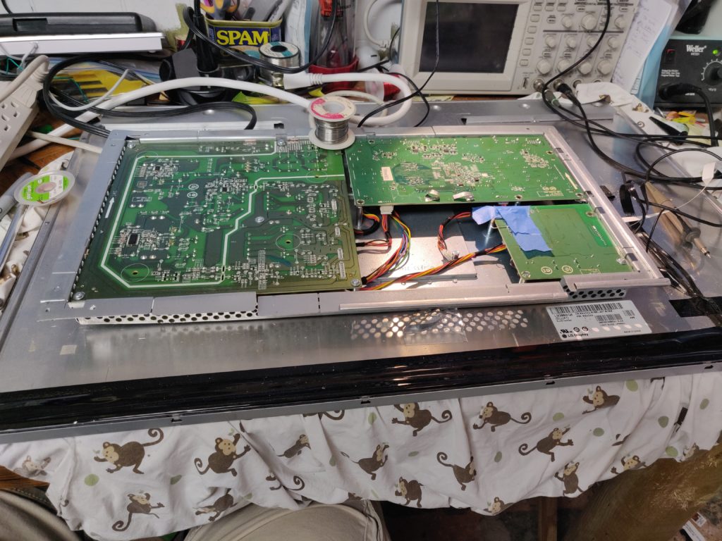
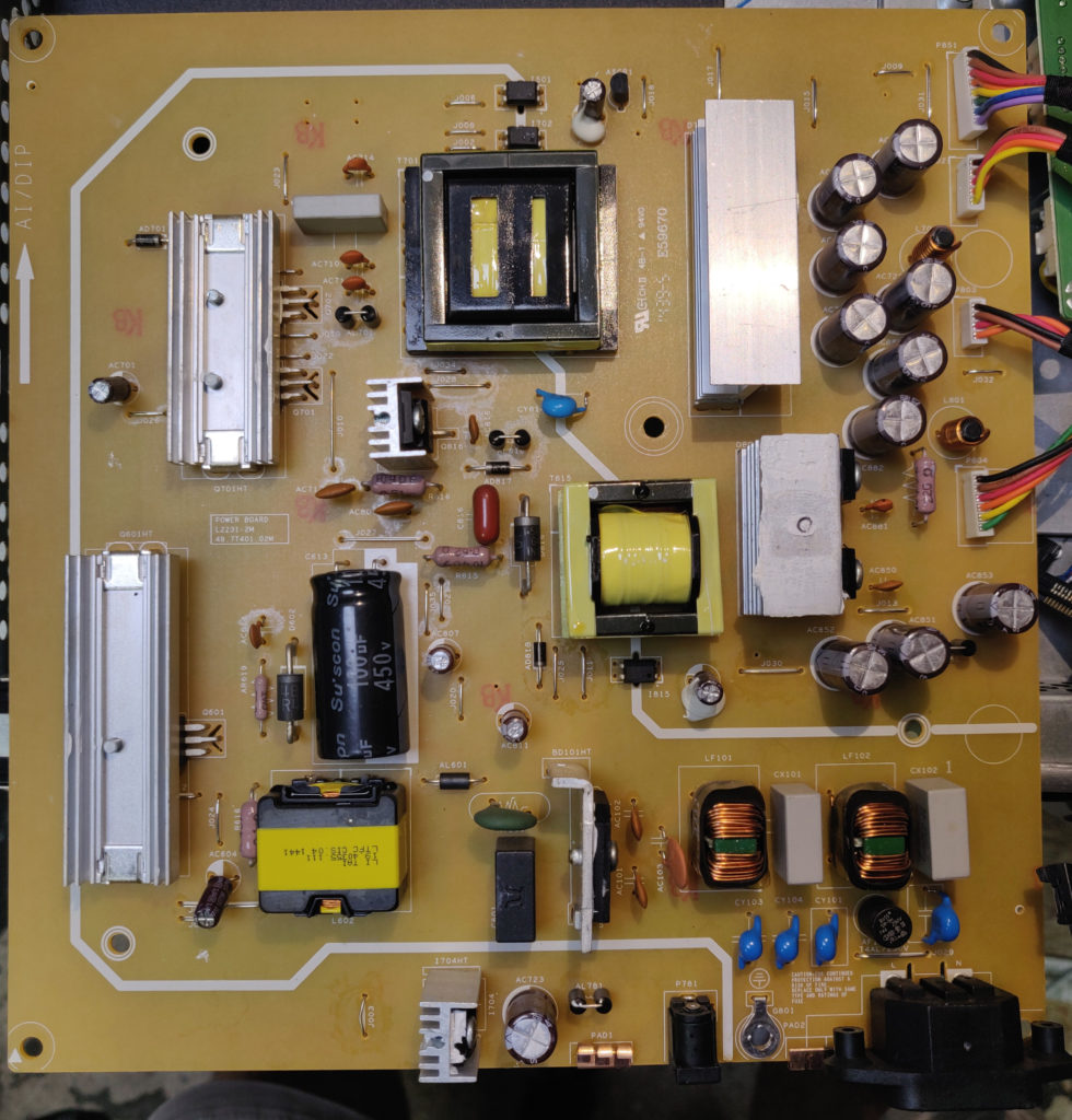
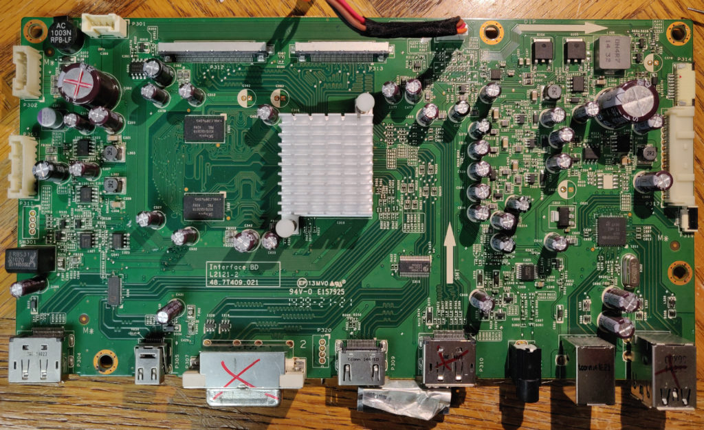
Inside the box are 3 large boards with well-defined functions. In the following, all locations and directions (top, bottom, etc.) are with respect to the photo above.
- Power supply board (L2231-2M 48.7T401.02M), top-left, generates voltages needed by the rest of the system
- Backlight driver board (L2259-1 48.7T408.011), bottom-right
- Mainboard or “interface board” (L2121-2 48.7T409.021), top-right, handles pretty much everything else between input from video sources to output to the LCD panel.
You can do a “which board is bad” level diagnosis without further disassembly at this point, but if you do need to remove the boards, in addition to the obvious screws there is another mating a heatsink on the component side of the power board to the metal box for additional heatsinking, and a couple of screw-in posts in the DVI connector pinning the interface board to it as well. Removing the boards makes it much easier to disconnect the cables as needed. Beware that with the protruding video connectors and ribbon cables, getting the interface board in and out is a bit of a Tetris game – watch the little ribbon cables and don’t force it.
The “Which board is bad” diagnosis
Power supply board
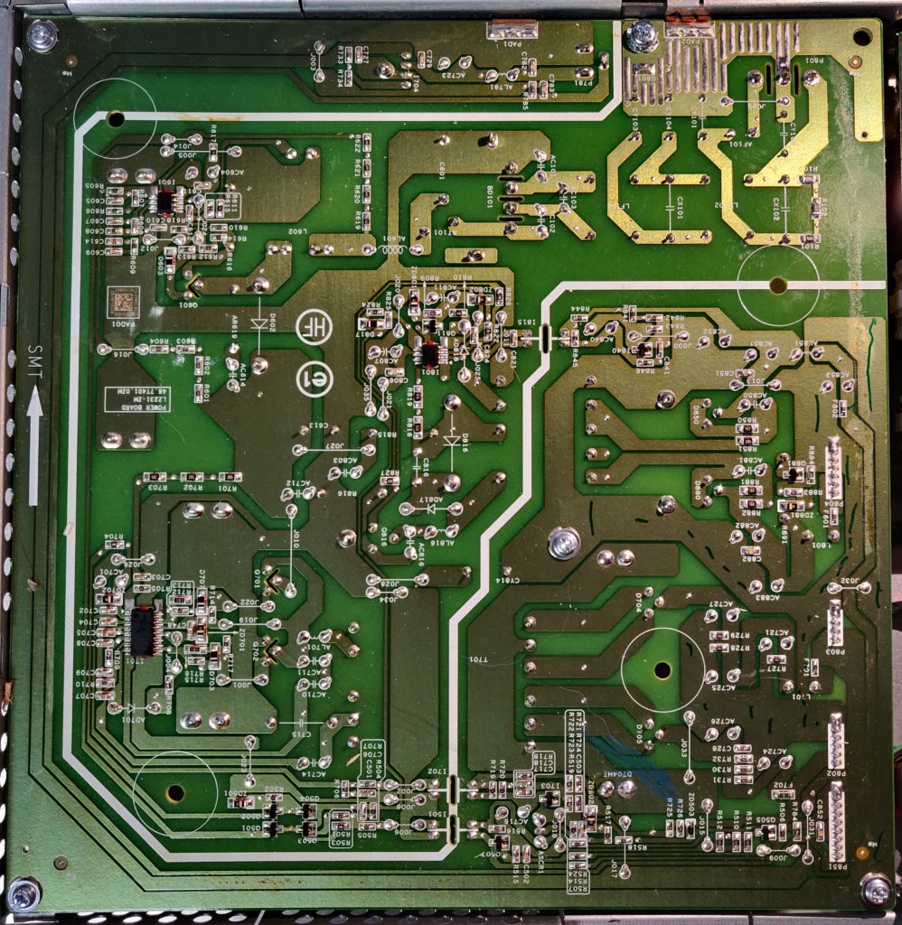
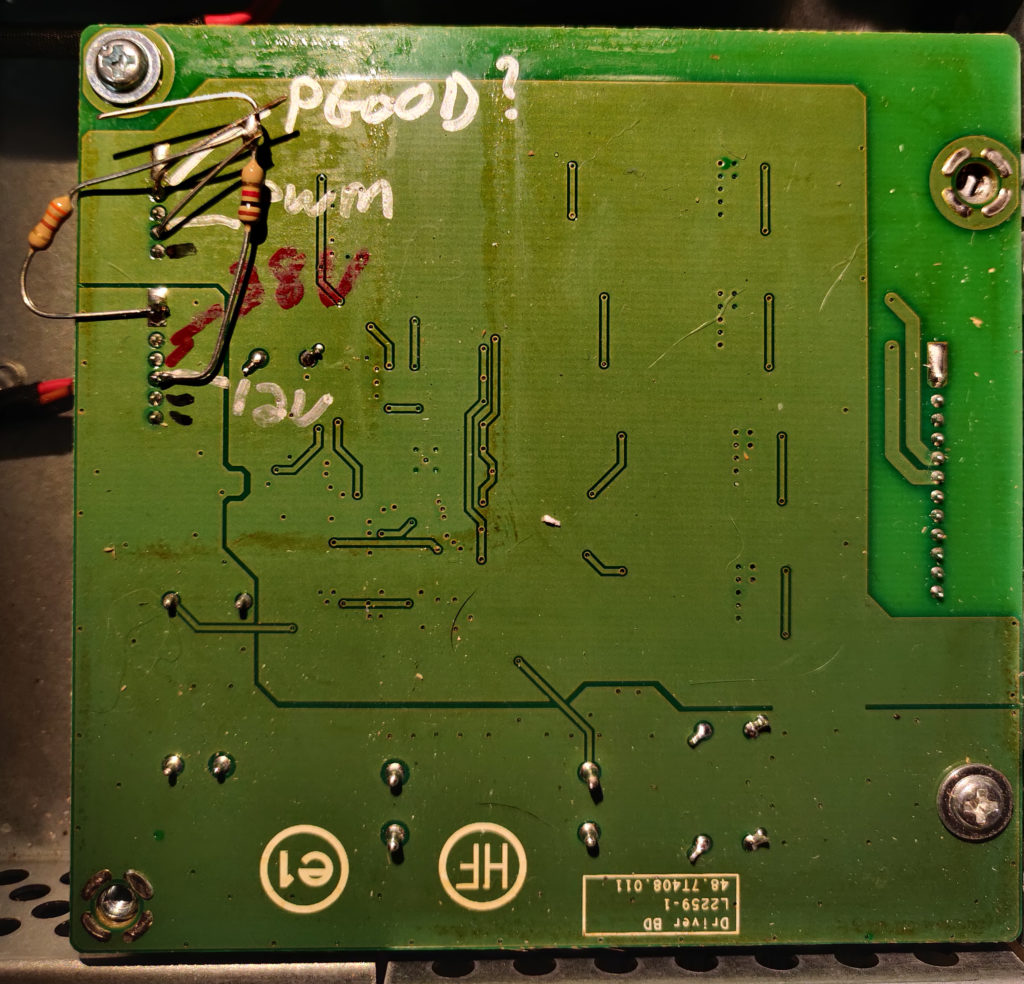
The power supply board is “on” and generating all of its voltages regardless of the power button, as long as the unit is plugged in. Needless to say, mains voltage will be present on at least portions of the board when powered, and potentially some while after on charged capacitors, so be extremely careful doing any diagnosis. The HV section is at least clearly marked off with a thick white line. With the interface board connected, you may hear a faint ‘ticktick, tick, tick’ sequence from somewhere near the mains cable right when it is powered up. There are a total of 4 cables exiting the righthand side, with easily accessible solder pads on the back (green/solder) side, outputting various low (<40V) DC voltages. From the back (green/solder) side, going down the line top to bottom (square solder pad first), the voltages should be:
(P804, 6 pins):
- GND
- GND
- GND
- 15.5V
- 15.5V
- 15.5V
(P803, 4 pins):
- GND
- GND
- 12.5V
- 12.5V
(P802, 5 pins):
- GND
- GND
- 12V
- 37.5V
- 37.5V
(P851, 8 pins):
- 5.0V
- 5.0V
- 5.0V
- GND
- GND
- GND
- 3.0V
- 0.0/2.4V (appears to be a feedback signal telling whether anything, nominally a sound bar accessory, is plugged into the 12VDC output jack)
Note these are nominal values and could vary a bit on different units, especially the larger voltages. Adjacent pins on the same cable with the same voltage are physically bridged together on the board and don’t need to be separately probed. Finally, all boards are grounded to the large metal box when screwed down, so it can be used as a convenient probe ground. If all of these look good, have a look at…
Backlight driver board
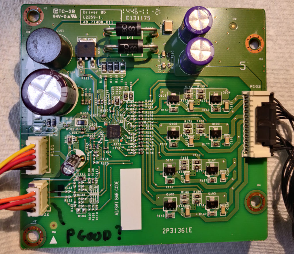
This board accepts two cables on the left; they are labeled on the component side only: P101 (5 pins, from P802 on the power supply), and P102 (4 pins, from the interface board) – and outputs one to the panel’s LED backlights on the right. Pinout of P101 matches P802 on the power supply; pinout of P102 (again, starting from the square solder pad) appears to be:
- ENABLE
- NC/Unknown (leads to a non-populated circuit on my board)
- PWM (brightness control)
- GND
To quickly test, assuming the power supply voltages are OK, you can disconnect P102 coming from the interface board and pull the ENABLE and PWM pins up to ~3V. I just used a resistor divider on the 12V power supply pin (12V -> 1k -> 330R -> GND) and connected its center tap to both pins. (Despite some oft-repeated Internet wisdom, simply disconnecting the control cable is not enough to force it awake, at least for this particular model.)
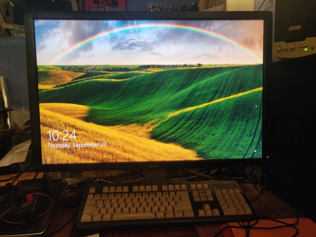
With this temporary hack done, the panel should visibly light (easily seen in a darkened room) whenever the unit is plugged into mains power, bypassing the interface board (including power button). If it lights, next possible culprit is…
Interface board
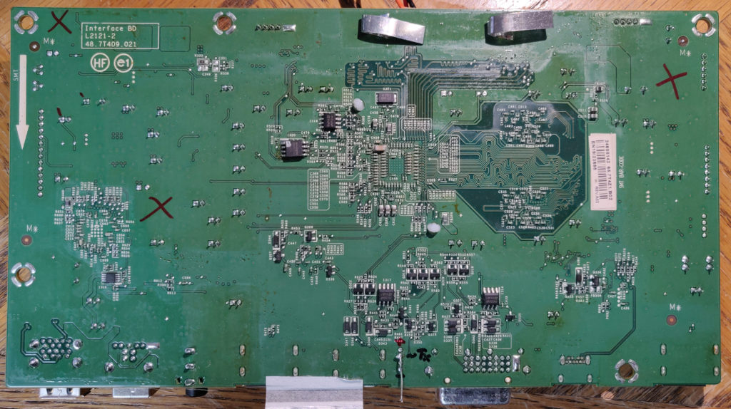
This is the brains of the whole thing, and unfortunately, if it’s got a problem (particularly under the media processor BGA), component-level diagnosis and repair may prove to be a tall order. What follows is pretty specific to my unit, but a functioning interface board should at minimum respond to / light the power button and animate the menu LEDs, regardless of whether the backlight board, LCD panel (“t-con” or timing controller board, hiding under a thin metal bracket on the panel itself) or card reader assembly are connected.
On my particular unit, the power button and LEDs appeared completely non-responsive. (Pressing a moist finger on the bottom of the LED/button board caused the LEDs to glow dimly, this doesn’t count.) After confirming the power button physically works and had continuity at the ribbon connector, I started poking around and found a debug serial port(!) on the non-populated connector P320 (nestled between the DVI and HDMI ports), that emitted text at startup. Its pinout, again from “top to bottom” in the photo (starting from the board edge) on the back/solder side of the board is:
- GND
- Rx (UART in from host)
- Tx (UART out to host)
- Vcc (3.3V?)
Beware, after buttoning everything up I discovered an inconsistency in my notes and can’t be 100% sure the serial port isn’t 5V; doublecheck before hooking up anything you care about. Connection parameters are the extremely standard 115200-8-N-1. The Tx pin needs a pullup resistor to Vcc (1k worked fine for me) to produce sharp rising edges on the signal and avoid garbled serial decoding. However, even with the signal cleaned up, there are consistent stray characters in the output where it looks like linebreaks should be. In any case, comparison of the startup output between the “dead” and replacement board show some differences.
“Bad” board output:
Ø Dual Flash Bank is disabled.!Init PCTL. April 27 2012<DDR3 - NT5CB64M16DP-CFFine tune WDQD: 0x%xine tune RDQSD: 0x%x¹,IFM measured RC-OSC Clock Value = 0x%xÝã'Calibrated RC-OSC Trim Value = %d8%Measured RC-OSC Clock = %d000HzõeUploaded LPM: %d bytes
cOtpSramInit OKÍLPM DC off!
“Good” board output:
 Dual Flash Bank is disabled.!Init PCTL. April 27 2012<DDR3 - NT5CB64M16DP-CFFine tune WDQD: 0x%xine tune RDQSD: 0x%x¹,IFM measured RC-OSC Clock Value = 0x%x¹'Calibrated RC-OSC Trim Value = %d7%Measured RC-OSC Clock = %d000Hz/jÔUploaded LPM: %d bytes
cOtpSramInit OKÍLPM AC on!:+STHDMIRX-REL_BSP_1.7H.5 - E24CT5_HDMIRXRLPM GPIO0 : 0 => DP_MINIê%**Athena Product Version 2.%d**Ä2¼DP1.2 Lib Version 1.1È09:46:43  Nov  7 2012]!HDCP Repeater Lib Version 0.7i10:34:12  Sep  5 2012yAudio_Cus_Mute %d zAudio_Cus_Mute %d zVWD Gen3: May, 2012ìAudio_Cus_Mute %d ø	*****SYS Lib Ver - V1.0 RC0Sep. 14, 2012 8:00 PM?OSD Lib Ver - V3.0.10July 22, 2008 02:23PMÞDRV Lib Ver - V1.0.00
Oct. 25, 2012 2:30 PMBSTDP93xx Athena UaSTDP93xx RD1 BoardWApplication Ver - Beta TCuSep. 14, 2012 8:00 PM?LG_WQXGA_LM300WQ5_SLA1DRAM code execution	 Î

Dual Flash Bank is disabled.!Init PCTL. April 27 2012<DDR3 - NT5CB64M16DP-CFFine tune WDQD: 0x%xine tune RDQSD: 0x%x¹PM restarted from SRAMÚLPM DC on!7+STHDMIRX-REL_BSP_1.7H.5 - E24CT5_HDMIRXRLPM GPIO0 : 0 => DP_MINIê%**Athena Product Version 2.%d**Ä2¼DP1.2 Lib Version 1.1È09:46:43  Nov  7 2012]!HDCP Repeater Lib Version 0.7i10:34:12  Sep  5 2012yAudio_Cus_Mute %d Audio_Cus_Mute %d VWD Gen3: May, 2012ìAudio_Cus_Mute %d
The bolding is added by me of course, but a couple differences to notice are the “LPM” messages and overall length. In the “good” board output, the first block of text (ending with “DRAM code execution”) is from a single poweron (plugin); the 2nd block of text occurs after powering the monitor off and on again using the power button. The bad board appears to halt prematurely following the “LPM DC off!” message. (Needless to say, since this board is not responding to the power button, we don’t get any separate “warm restart” output either.) We’ll get into the details in a bit, but the LPM is the “Low-Power Mode” subsystem, which includes some dedicated power rails and and a low-speed microcontroller core running on the media processor IC that generally handles mundane tasks such as scanning for power/menu key presses, cable detection and power management. My best guess is this hints at a power issue on the mainboard (LPM domain supply not turning on, or not being detected by the processor), but since I ultimately solved my issue by just replacing the entire mainboard, I don’t plan to dig further into it at the component level.
Button/Menu Board Assembly
I didn’t bother taking a picture of this, but it’s a small pair of PCBs connected together by ribbon cables, consisting of a physical power button with internal LED on one, and a set of 5 “soft” buttons/LEDs on the other. Operation of the power button can be confirmed pretty easily via continuity test on the ribbon cable while pressing the button. The softbuttons are a bit more complex, but don’t prevent the basic video function from working and can be diagnosed as a culprit if “everything but menus” works.
T-Con (TFT Controller or Timing Controller) Board
I actually don’t know much about this one, and never liberated it from beneath its shield, but more-or-less every LCD panel has one in some form; it’s responsible for massaging the video data stream from the mainboard into the individual row/column drive chips festooning the edges of the LCD glass itself, and in most cases generating the necessary drive voltages. Do your own web searching if this is still on the table as a possible culprit, but it sounds like common (repairable) issues with a T-Con board will affect the picture as a whole and may include color or brightness shifts or lines across the entire display. In general, T-Con board issues cannot cause glitches localized to specific image regions.
Firmware Dumping, wait, what?
Oh yeah, I guess it’s obvious in retrospect, but did you know monitors have firmware? A quick web search on the debug output strings above reveals a couple reports of this media processor in similar monitors spontaneously bricking by corrupting its firmware, which resides on a small serial Flash chip on the board. In particular, this detailed report inspired me to dump and compare the firmware between the good/bad boards and see if this was the cause of failure. Long story short, it wasn’t – although there were minor byte-level differences, possibly due to different compiler versions used to build it, there were no obviously missing or corrupted blocks, and reflashing the old board with known-good contents didn’t have any effect. However, I now have two different FW dumps from this monitor model.
Despite the byte-level differences, examining the strings in both dumps using a ‘strings’ utility reveals only one identifiable difference in version strings. The content suggests a number of separate libraries, each with their own versioning, go into the build, although the association between a version string and identifiable library name is not always evident, and there are probably more that don’t include an explicit human-readable version string in the binary.
Now that we’ve got ’em, are these dumps remotely useful? There are scattered reports that various issues with this display, in particular compatibility issues with DisplayPort 1.2+ (e.g. hanging on/off with a blank screen and requiring power cycling) that are FW version dependent. Unfortunately I can’t say if either of these versions helps with that, but both are linked below in case you want to give it a go. The only obvious version string difference is in a string near a reference to “Dp1.2”, which is promising at least. The respective identifiable version strings are:
"Older":

VWD Gen3: May, 2012

Init PCTL. April 27 2012

09:46:43  Nov  7 2012

10:34:12  Sep  5 2012

Dp1.2
20130807
M1T103
VK278

STDP93xx Athena U
STDP93xx RD1 Board
Beta TC
Sep. 14, 2012 8:00 PM
cASTDDVIRX_1
cASTHDMIRX_1
SAMSUNG_WUXGA_LTM240W1_L01

DP1.2 Lib Version 1.1

HDCP Repeater Lib Version 0.7
V3.0.10
July 22, 2008 02:23PM
V1.0 RC0
Sep. 14, 2012 8:00 PM
V1.0.00
Oct. 25, 2012 2:30 PM
"Newer":

VWD Gen3: May, 2012

Init PCTL. April 27 2012

09:46:43  Nov  7 2012

10:34:12  Sep  5 2012

Dp1.2
20140305
M1T104
VK278

STDP93xx Athena U
STDP93xx RD1 Board
Beta TC
Sep. 14, 2012 8:00 PM
cASTDDVIRX_1
cASTHDMIRX_1
SAMSUNG_WUXGA_LTM240W1_L01

DP1.2 Lib Version 1.1

HDCP Repeater Lib Version 0.7
V3.0.10
July 22, 2008 02:23PM
V1.0 RC0
Sep. 14, 2012 8:00 PM
V1.0.00
Oct. 25, 2012 2:30 PM
Just beware that the reflashing procedure is not for the faint of heart as it requires desoldering the Flash chip (labeled I319 on the board; exact partnumber and capacity may differ – mine had a 4MByte Winbond 25032FVSIG) and wiring it up to custom hardware (a 3.3V Arduino will work fine). While the media processor datasheet hints at reflashing capabilities through debug serial port commands and even HDMI/DisplayPort (?!) via a software tool called “EZ_Display UP”, both methods are rather well undocumented, and even Dell will have you mail the whole thing back for replacement rather than offer a software flash tool for things like the DisplayPort update.
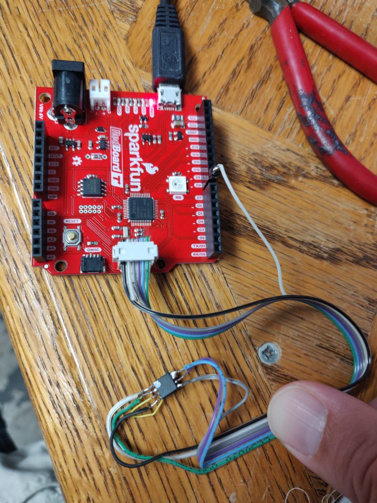
The chip is a standard serial Flash (NOR Flash, DataFlash, etc.) for which a number of tools exist. Personally, I used an Arduino-compatible SparkFun RedBoard and the spi-flash-programmer library by Nicholas FitzRoy-Dale. With this combination, dumping the whole chip takes about 8 minutes, writing it takes quite a while longer (I just left it go overnight). If you do end up doing this, working out which pins correspond to the requisite serial lines on your chosen board is left as an exercise to the reader. On the RedBoard and likely others, the serial pins on the 6-pin ICSP header are the library default and any available digital pin can be chosen for /CS (D8 being the default). Just beware that on most of these chips the /WP and /HOLD pins need to be pulled high (3.3V) and cannot be left floating. The dumps linked above are 512Kbit or 4,194,304 bytes (addresses from 0 to 0x3FFFFF).
Some More Nerdy Details
Media Processor
The heatsink-enshrouded media processor on the mainboard is the STMicro STDP9320-BB or similar, also known as Athena (“Premium high resolution multimedia monitor controller with 3D video”). While some fairly useless “product brief” information about this chip is officially published, the actual datasheet is a national secret and probably available only under the strictest of NDAs, although it’s also available from unofficial sources online if you know where to look.
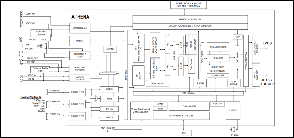
The chip documentation is a mildly interesting read, for those of us into that sort of thing. Of particular – if now mostly hypothetical – relevance to my board’s issue was the boot process of this chip and what could cause it to halt prematurely. To wrangle the various high-horsepower on-chip video hardware, the processor includes two separate microcontrollers (OCM – On-Chip Microcontroller), a 250MHz jobbie (“Mission”) handling the bulk of the operation, and a smaller, “LPM” (Low Power Microcontroller) at a paltry 27MHz handling basic user interface and power management tasks. The single serial Flash contains firmware images for both. Interestingly, the powerful Mission OCM boots first, controlling the process and in turn booting the LPM, rather than the other way around.
On my particular board, the evidence points to an issue with the power management signal from the LPM – “(MAIN_POWER_ON), which is used to control power to the mission power domain through external switching circuitry.” I don’t know how common this failure mode is, but as it started to sound like a tail-chasing exercise of finding the lifted BGA ball or shotgunning FETs at random without a schematic, a fresh board off the flea-est of Bays sounded too good to pass up.
A minor thing that stuck out at me is that with all this grunt and spare Flash on board, the PCB is still festooned with small EEPROMS (24Cxxxx) around the individual video and USB interface ICs, or that there are even discrete chips for that. On a quick look, the one near the HDMI port is tied directly to the port, and several existing video cable standards including HDMI explicitly use small I2C EEPROMs to store display identification data (EDID). It’s probably cheaper overall to stuff discrete chips for it than try to emulate them on demand.
Display Glass
The actual LCD in this monitor is made by LG, part number 0X3CH4, for which online replacements seem to exist (the sticker also contains the part-numbery value LM300WQ6, which turns up more in the way of likely replacements). In fact, the marriage between the display and the video “brains” board is a loose one and the signaling to the T-Con board is fairly well standardized; many of the images online for the LCD panel show various other video boards in use. YMMV of course, but if anyone reading this succeeds cobbling a working screen together using the mainboard from an unrelated one, I’d love to hear about it.
Leave a Reply