While procrastinating on my current year+ long “couple long weekends” project, in which I’ve clearly bitten off more than a post-kids me has time to chew, I set my sights on a stupid-simple project I could actually complete :-) This is an adhesive stick-on fish tank heater for nano aquariums. The thin PCB trace heater just sticks onto the outside of the glass, entirely out of contact with the water and without consuming any valuable space inside the tank.
If you’ll recall a couple posts back, I found that it’s curiously hard to find small heaters intended for small (nano/pico) aquariums that don’t suck. Preset temperatures (or no temperature regulation whatsoever), not being invisible, short life span, not being invisible, sketchy mains lead going right into the water, and not being invisible are but a few ways in which they suck. So, I made an invisible one that doesn’t go in the water.
Okay, so it’s not technically invisible, but this one can be easily concealed and does take up -zero- space inside the tank.
This is not a product for sale, but the design files are published under a Creative Commons license if you want to roll your own.
In a nano tank, every cc is precious, and well, your typical heater options for small tanks are a big ugly hunk of plastic or a big ugly tube of glass intruding into the already limited space. Everyone has the silly peel-and-stick liquid crystal thermometer on the outside of the glass though, because however sketchy it looks, they actually work pretty well. So, why not a heater that works the same way?
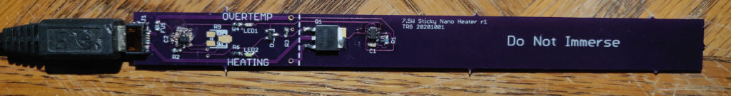
So to test it out I made the Sticky Nano Heater (not a real product name, suggestions welcome), a skinny circuit board with a 7-10W resistive heating element (PCB trace heater), MOSFET, and a pair of resistor-adjustable thermostat chips to control it. The board is adhered with double-sided tape to the outside of the glass in an unobtrusive location, such as along the substrate, and uses the glass itself as a heat spreader.
Besides “dirt simple project I could bang out quickly”, some design details are:
Dryness: No parts touch the water. Not the heating element, not the thermal sensor, not the power cord. This simplifies the sealing requirements to “nonexistent” (a splash-proof cover or coating is still not a bad idea for those water-change oopsies that never happen.)
Power: Just to keep things simple and avoid having to muck around with mains voltage near things that get wet, the power plug is USB and runs off one of the numerous spare phone chargers found sitting in a drawer somewhere. This keeps the really energetic wall pixies a good 3-6ft away. A common 5V/2A USB charger nominally delivers 10W, but I initially aimed to draw closer to ~7.5W just because I don’t trust the ratings on cheap phone chargers and neither should you. (I ended up cranking it back up to 10W for the 2.5-gallon test tank, but more on that later.)
Temperature Sensing: On one end of the PCB, away from the heating element, is a simple thermostat IC, the cheap and cheerful MCP9510 (or TMP709). It provides a digital output that cycles on/off as the temperature exceeds a resistor-set threshold, with a ~2C hysteresis. This is coupled to the glass by a copper thermal pour and via-stitching on the PCB. On this prototype version, the temperature setpoint is adjusted by twiddling a small pot, but providing a few discrete options is probably simpler for real-world users. A second thermostat on the heating element itself limits the maximum surface temperature to a user-set value (useful for very tiny setups and/or plastic tanks).
Safety Features:
- The main one, pun intended, is no mains wire going into the water.
- The second sensor, coupled directly to the heating trace by a via and small thermal pad, limits maximum surface temperature in case of detachment from the tank, tank materials with poor thermal conductivity, or other adversities. While some informal testing with an outdoor outlet, some dry leaves and a warm day showed that 10W over this surface area doesn’t really pack enough punch to be a serious fire hazard, this feature cheaply protects the heater and nearby surfaces from heat damage, keeps double-stick tape happy, and allows the heater to be freely used on those plastic tanks that are inexplicably the rage these days (YMMV on actual heat transfer of course).
- A surface-mount fuse inline with the power supply. While the USB charger “should” current-limit in the event of a board-level fault, this will blow if it doesn’t, or if the charger faults in a way that sends wall voltage down the wire. (*the prototype shown uses a tiny 0603 fuse that is not rated for 120VAC; this is fixed in the published revision).
Looks like a snakeoil Kickstarter pitch – does this actually work?
Surprisingly well, albeit with a couple caveats I’ll explain in a moment.
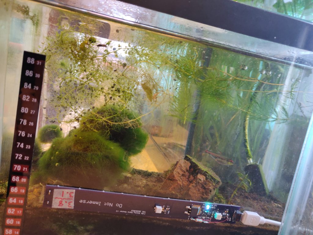
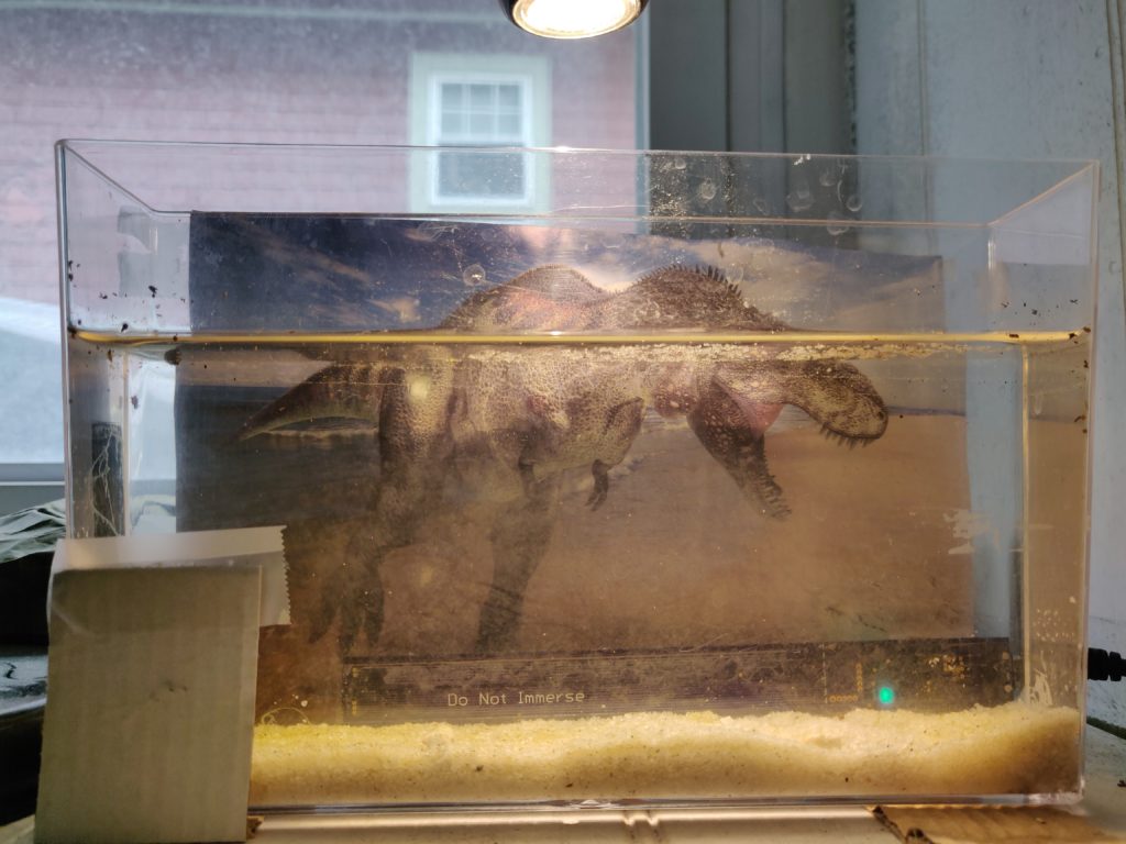
Given I just bashed out a suck-it-and-see prototype rather than do any kind of actual thermal modeling, I was a little worried that the glass and tape would not be thermally conductive enough, the tape would immediately overheat and lose its stick, or that the glass would prove too conductive relative to water, causing the proximity of heating element to the temperature sensor to disturb the measurement. On a 2.5 gallon glass betta tank used for test, the outer surface of the heater part of the PCB gets barely warm to the touch on a filled tank (vs. scalding in free air), and the glass immediately outside the contact area is not perceptibly warm to the touch. The water very effectively sinks the heat; no noticeable heat transfers across the only-an-inch-or-so of glass between the heating element and temperature sensor. So far, I’ve just used plain Scotch brand double-stick tape to attach them to glass and plastic, and this has stayed very well stuck while seeming to have negligible effect on heat transfer. Likewise, the tank sinks heat effectively enough that I’ve seen no need to insulate the outer surface of the heater or surrounding glass against excess heat loss.
The only major caveat to the prototype shown is that the oft-quoted “3-5 watts per gallon” (or ~1 watt per liter) rule of thumb kind of breaks down for nano tanks as surface area begins to dominate volume, so the 10W (max) available from a standard USB charger just isn’t a lot. On my 2.5 US gallon (10L) test tank, 10W is really just enough to take the edge off a drafty windowsill and chilly winter thermostat setting, raising the temperature only a handful of degF on average. Of course, slapping on a second one to double the wattage is easy enough, but with 20+ gallons still being considered “nano”, festooning a tank with them kind of defeats the purpose. If I were to do up another one, I’d probably base it on a beefier power source of ~25W or so.
This leads to the second, more minor caveat, which is that PCB trace resistors are rather low precision, the actual resistance (and thus heat output) from a given supply will vary between batches and even between boards. Across two batches of 3 OSH Park boards each, one had a spread of 4% resistance and the other about 50%, and I can’t tell you which of those cases is the outlier, if any. As long as the power supply has enough grunt to cover reasonable variations, this is not a big deal and the thermostatic control (a way to not suck, remember?) will maintain the right temperature regardless. But, it becomes an issue if you’re trying to eke every last drop of power from a marginal wall-wart without toasting it.
Design Details and Lessons Learned
Below is the full schematic. There’s not a lot to it (and the long zigzag at right represents the PCB trace heater, of course), but it’s still “complex” compared to the industry standard. Hey, at least it doesn’t have IoT and a phone app!

This is something an EE1 can probably design in their sleep, but a few minor real-world gotchas worth noting.
- USB phone chargers are switching regulators and can be noisy, and USB cables vary dramatically in quality. In particular, long or poorly-made cables will exhibit a significant voltage drop when the heating element is on. Besides reducing output power, this can cause the tank temperature sensor to oscillate as its interpretation of the setpoint resistor is somewhat voltage-dependent, at least in the short term (the voltage drop when the heater turns on causes the setpoint to appear slightly lower, turning the heater off, which causes the voltage to rise again, etc.). The RC filter (R8, C2) on its power rail mitigates both the inherent noisiness of value-engineered USB chargers and the voltage ripple of heater operation. Note that I didn’t bother with filtering the overtemp sensor, since (you shouldn’t be tripping it anyway and) its exact setpoint is less critical.
- The outputs from the two sensors are ANDed together with an explicit gate vs. using some more clever scheme with diodes. Mainly this allows the all-important tank temperature sensor to have minimal output loading by not driving the indicator LED directly. This avoids self-heating of the tiny sensor IC, which can be significant even at a handful of mA for the tiny die inside. Again, the overtemp sensor is less critical and does drive an LED directly, although at a fairly low current.
- It doesn’t show on the schematic, but I designed the trace resistor to err on the high resistance side, and added a few sets of trim jumpers in the form of closely-spaced vias that could be soldered across to short neighboring traces. This came in handy as the trace resistors had a fair bit of tolerance and it became clear that I needed to extract as much heating power from the power source as possible.
- Remember that the heater side needs to press flush against the tank, so all components (including indicator LEDs) are on the other side of the board and likely facing away from the viewer. To make the LED indication visible I just added openings in the soldermask on both sides of the board and mounted the SMT LEDs upside-down. This produces a pretty neat, subdued effect with the LEDs producing a diffuse glow through the board material in the shape of the soldermask opening. You can buy SMT LEDs specially designed for downward-firing, but simply flipping most standard ones over seems to work fine too, and shining into the PCB material they are plenty visible from both sides.
- Yes, this could totally be done on a flex PCB for contoured tanks. All of mine happened to have flat surfaces handy, so I didn’t bother.
Leave a Reply