Category: gEEk
-

Silly Sideprojects: The Lighting-Up-Crotch Snowman!
Finally, a blinky project of the scale I can actually bite off these days (unlike pre-kids), but it requires a bit of backstory. My wife’s mom absolutely loves Christmas, and like many families, their Christmas is full of tradition. It just wouldn’t be Christmas without egg dish, Dead Thelma Neuboldt’s Merry Christmas Chicken in the…
-
Build a Minimalist DIY Vibratory Rock Tumbler
My son and I have gotten into rock tumbling a bit, so I put a small vibratory tumbler on my “would be nice” holiday wishlist. So, apparently this hobby has gotten popular lately and these things can’t be had for love or money. Maybe for lots of money, but I wasn’t ready to drop 400…
-
Notes To Myself: Remote Couch Gaming with RPI5 / Moonlight
Hey Future Tim, in case you ever need to set it up again, here is a guide to setting up game streaming from a beefy desktop PC (game host / backend) to a Raspberry Pi 5 (game display client / frontend) with low latency, both for the input devices (keyboard/mouse or controllers linked to the…
-
3D-Printable replacement plastic coupler bit (stem driver) for Kohler Rite-Temp(R) shower faucet handles
Go for a shower, and the new (professionally installed just over 1 year ago) Kohler shower faucet handle just spins in a full circle with some rough detents without any water coming out. After figuring out what the actual product is and how to extract it from the wall (nary a screw or screw-hiding cover…
-
Exactly how much work is a half-assed job?
If you tend to work smarter, not harder, you may at some point in your life have been accused of doing a half-assed job. But what, exactly, does that mean? How much work are you doing? How much energy are you putting into it?
-
Solved: Control Raspberry Pi media center (Kodi) with Roku TV’s remote over HDMI CEC
TL;DR if you already figured out the documented stuff: Enable 2-way CEC (keypresses from TV remote to attached device) in the Roku secret menu: Quickly (within ~ 5 seconds) press Home 5 times, rewind, down, fast forward, down, rewind, and “Enable CEC Remote Control”. A further update: After doing all this, I found Kodi on…
-
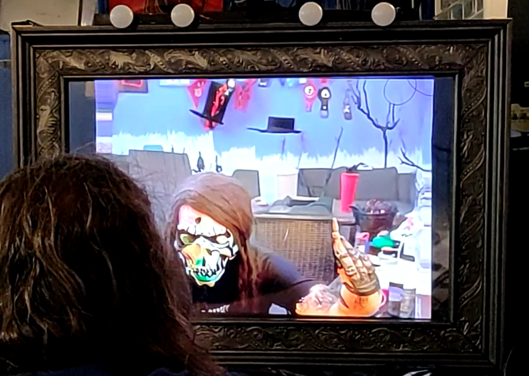
Spookifying Haunted Mirror build using Stable Diffusion
For this Halloween, I built this haunted mirror display for the porch that turns any trick-or-treaters extra spooky. Using the voodoo power of AI, those who gaze into the mirror will be treated to a visage of their best Halloween self. See below for code and build tips if you’re interested in making your own!…
-
AllElectronics “Mystery Infrared Device” with LIRC
NOTE: This device is no longer sold; rescuing this information before it disappears from various caches. Description of the device from AllElectronics: Our best guess is this is an infrared receiver/ transmitter for use with televisions or other remote-controlled equipment. Made for OnCommand™, it consists of a small black box, 2″ x 1.95″ x 0.6″…
-
CNC milling custom 40DP timing belt “gears”/pulleys
Woo, it’s been a long time since I messed with pick & place stuff. Bad Tim. An irritation I have been having is making everything work using reliably sourceable, off-the-shelf parts (not lucky eBay/surplus finds). In particular I’ve found small “tin can” stepper motors are hard to source in small quantities repeatably, and once you…
-
Fun with cheap TV-tuner dongles and Software Defined Radio (SDR)
So, last week I joined the bandwagon of exploring software-defined radio (SDR) via one of those super-cheap Chinese TV tuner USB sticks. In a nutshell, the idea of SDR is that, rather than the traditional approach of building dedicated radio receiver hardware for each possible RF band and modulation type (here’s your AM radio, here’s…
-
Notes to myself: Using EnergyMicro EFM32 with GCC open-source toolchain
The EFMs can be used with many different toolchains after installing EnergyMicro’s “Simplicity Studio” package, which includes board/chip support packages and some code examples. EnergyMicro’s application note AN0023 has an overall good overview of setting up an Eclipse + GCC (CodeSourcery) toolchain. Nevertheless, in attempting to replicate this process on my Win7 system (work PC;…
-
Buying Parts
-
Solved: Can’t connect to high (>10) Windows COM ports / cleaning out unused COM ports
Problem: Windows, and many Windows apps that use serial (COM) ports, have various problems accessing “high” numbered COM ports. I cannot find an authoritative or quantatative definition of “high” (and it may depend on your app), but I have seen apps start failing after COM8, COM9, COM15… anything in the 20s is asking for trouble.…
-
Solved: SL4A force close when calling recognizeSpeech
Problem: SL4A crashes upon the first call to recognizeSpeech() : com.googlecode.android_scripting stopped unexpectedly (Force Close). The corresponding Android log via adb shell #logcat: D/AndroidRuntime( 2785): Shutting down VM W/dalvikvm( 2785): threadid=1: thread exiting with uncaught exception (group=0x4 0018560) I/ActivityManager( 1429): Starting: Intent { act=android.speech.action.RECOGNIZE _SPEECH } from pid 2785 E/AndroidRuntime( 2785): FATAL EXCEPTION: main E/AndroidRuntime(…
-
Computer-controlled RGB LED Buckyball
Everyone and his brother has built LED cubes before, and while they are unmitigatedly awesome, I wanted to try something a little different. As far as I can tell, nobody has made an LED buckyball before! And of course, the requirements for such a large, sparse shape are a little different. In a typical LED…
-
Fixing an Acer AL2216W LCD Monitor (Delta DAC-19M010 power supply, bad caps)
There are several dozen of this model of monitor at my work since last year or so; the other day I found one on top of the dead electronics plunder pile recycling bin, looking brand new. Googling the model # and terms such as “problems” or “repair” or “won’t turn on” revealed pages of discussion…
-
Slam Stick: dissected!
Woot! It sounds like a gadget I designed will be featured in next month’s EDN magazine (Prying Eyes column). This must be some kind of ironic career turning point: I landed a job by reverse-engineering other peoples’ stuff; now people reverse-engineer my stuff.
-
UVLO, Comparators with hysteresis (now with 20% more equations!)
The Mosquino board is intended to operate from very low-power sources, such as RF, vibration energy harvesting and small thermal gradients (e.g. body heat). Although the ATMega and the rest of the circuit can be put to sleep at < <1uA once they have reached legal operating voltage, many semiconductor circuits fail this test with…
-
Motorized SMT tape-and-reel feeder for DIY pick & place
Despite the impact of work, wedding planning and Super Metroid fan-hacks (not necessarily in that order ;-) on my freetime, my scheme to design a DIY-able open pick & place system is starting to come along. So far, there is a proper vacuum placement head, a rough idea of what the software architecture might look…
-
Tape Sprocket Creator
This is a free (open source) Python script for creating feeder sprockets for e.g. perforated tape or film advance. I wrote it for myself to generate SMD tape-and-reel feed sprockets, but it might also be useful for making replacement sprockets for 8/16/35mm film, microfilm and paper-tape systems whose original reader hardware no longer exists or…