Everyone and his brother has built LED cubes before, and while they are unmitigatedly awesome, I wanted to try something a little different. As far as I can tell, nobody has made an LED buckyball before!
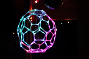
And of course, the requirements for such a large, sparse shape are a little different. In a typical LED cube design, the leads of the LEDs themselves form the structural members and support base of the cube – the lead lengths more-or-less set the size and density of the cube, and since it sits on a large surface area, there’s plenty of room to bring out plenty of signals and drive them from a single many-pinned microcontroller (usually via Charlieplexing). In a large, sparse hollow sphere, the wiring for Charlieplexed LEDs would get unwieldly pretty fast. So instead, I used a bussed approach where each LED sits with its own tiny microcontroller on a serial bus, with a unique address programmed into each one. Such addressable “smart pixel” LED nodes have been around for a while and available off-the-shelf, but for various reasons (outlined below), I opted to design my own open source (GPL) version, dubbed das Blinkenlichten, and used these for the project. These nodes sit on a 3-wire (power, data, gnd) bus and speak over a self-clocking bit protocol. The ball contains 90 such nodes; one for each of the 60 junctions of the buckyball, plus 30 more in the “long” beams of the ball (more on that later too).
Sidebar: Addressable RGB LED nodes
Addressable “smart pixels” or RGB LED nodes have been around for a while; in the hobbyist community, BlinkM is probably the most well-known. However, at close to $13 a pop, a deployment of any significant number of these adds up very fast. In addition, the code was/is very much proprietary – not only closed source with dire warning against reverse-engineering, but only allowed for noncommercial applications at that. As of late 2004, there was really not much in the way of very inexpensive nodes or open-source designs to pick up and build on one’s own. Add to that patent issues surrounding many of these products (including pretty much all I2C-based designs), and the situation for open blinky hardware was bleak indeed. So I rolled my own that was dirt-cheap, minimal wire count and GPL’ed. By happy coincidence, it also avoids all the RGB LED control patents that I am aware of. Luckily, as of late 2011 there are many more inexpensive, open-source and even microcontrollerless (shift-register based) blinkies available in single or strips, so go nuts!
Buckyballs:
In real life, buckyballs are spherical molecules composed entirely of carbon. The LED ball models the most well-known of these molecules, carbon-60 (buckminsterfullerene), consisting of 60 carbon atoms. These atoms are arranged such that their bonds form 12 polygons and 20 hexagons, with one carbon atom at each vertex. The stitching, and often coloring, of soccer balls (footballs outside the US) mimics this structure.
Construction details:
I wanted the ball to consist of basically nothing but light – i.e. a bare minimum of visible wiring, electronics or any other opaque portions. Thus the light from the tiny LEDs would have to be well diffused throughout the entire structure. Playing around, I found that hot-glue sticks make almost perfect LED diffusers, and wasted no time cleaning out the local art&craft store’s supply for the ball’s structural elements. In retrospect, this was not the ideal solution: despite anything you might hear about the buckyball being a magically strong shape, it’s still not enough to hold the weight of 90 hot-glue sticks and electronics without sagging into more of a pear shape. In the end I had to add some internal “guy wires” (monofilament fishing line) to help it hold a spherical shape. As you can see, it’s still not perfect, so I’ll have some adjusting to do!
The ball consists of 12 pentagonal sections totaling 60 sticks, and 20 hexagonal sections formed by connecting 3 sticks between each neighboring trio of pentagons.
To create the physical ball, I needed some kind of scaffolding to hold the ball in shape during various stages of (in)completion, and ideally serve as a construction guide. For this, I bought a cheap inflatable soccer ball on eBay, blew it up, and assembled the ball around it in pieces. The markings on this ball (a promotional item for a foul-tasting yet inexplicitly popular domestic beer) are not 100% faithful to a real C60 molecule; the pentagonal sections are a bit small, resulting in the spokes between them (forming the hexagons) being a bit longer than the pentagon segments. I’ll just refer to these as the “long” sticks from now on.
First, I assembled all the Blinkenlichten boards with a 5mm LED. Each board is about 10mm square and can sit flush against the end of a glue stick with only the solder tabs sticking out. Each of the 60 sticks forming the pentagons are end-lit, with the LED node installed by drilling a hole in one end the diameter of the LED and shoving it in. The remaining 30 “long” sticks (to form the hexagonal sections) have a hole drilled in its middle and the LED inserted perpendicular to the stick. I’ve found that using a drill bit a tiny bit smaller than the LED itself works well: the drilling action heats up the stick enough to partially melt the inner walls of the hole; quickly shoving in the LED after this allows the walls to stretch slightly to accommodate it, then glues it tightly in place.

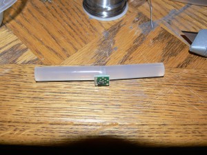
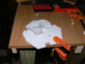
I first built the required number of pentagonal sections, with the length of each side matching that printed on the soccer ball. To do this, I made two simple templates in Inkscape and printed them out. One consists of two lines intersecting at 108 degrees (the interior angle of a pentagon), indicating the length to cut each stick to and the angle to cut the end at so that the 5 sticks will sit flush against each other when assembled. The other is a template for laying up the pentagon itself. A box cutter knife made short work of cutting the sticks to the right size and shape. With all the sticks cut to shape, I used more hot glue (for its intended purpose this time) to assemble the sticks into pentagons, being sure to fill in any gaps where the sticks mated.
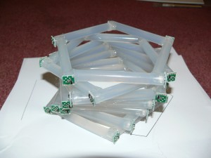
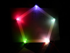
With all 12 pentagons assembled, I wired their power, data and ground terminals together using 3 runs of color-coded magnet wire. I made a complete ring with each – although this was not strictly necessary, it provides two parallel current paths between any two points around the pentagon. Not a bad idea since the ones nearest where the power/data cable will plug in will be passing a lot of current. To avoid any surprises later, I quickly clipped the Arduino (running a simple test loop) to each assembled pentagon to make sure they were working. Finally, I tacked the wires together and onto the backside of each pentagon with hot glue. While I had the magnet wire handy, I took this opportunity to solder lengths of wire to each of the 30 “long” sticks as well.
With the pentagons assembled and wired, I began assembling them onto on the inflated beach ball, adding the “long” sticks in between as needed. For this I just kind of winged it to avoid tolerance stack-up, marking and cutting one stick at a time for a good fit. After cutting to length, I cut a V-shaped notch in both ends of each stick so that they would mesh well with the pentagon corners they attached to. These were similarly glued into place, squeezing in extra hot glue to fill in any voids.
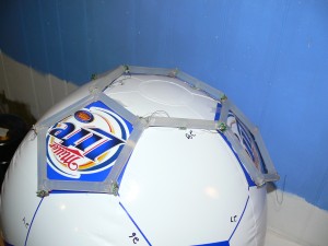

Finally! The buckyball looks like a buckyball. The beach ball was deflated and removed. By this stage each pentagon was already bussed together, so wiring consisted of using all the pre-wired “long” sticks to bridge neighboring pentagons together, folding or trimming any excess magnet wire and tacking it to the back of each stick (i.e. the inside surface of the ball.) After a final electrical test with the whole ball assembled, I sealed in all the LED boards and solder points with (you guessed it) more hot glue, made a hanger out of metal rod and cut two pieces of plexiglass to serve as the top and bottom supports for the rod. Bends in the hanging rod prevent the ball from sliding free of the rod or stretching out of shape.

Electronics & Programming:
After some brief forays writing effects code in Processing and C (to run directly on the Arduino), I decided to write the visual effects script in Python for the most flexibility. The effects script outputs serial data to an Arduino (for the blog cred, yo), which serves as the bridge between the PC and the RGB LED array. Commands are sent as 3-byte packets to the Arduino consisting of a sync byte (0x55) followed by the Blinkenlichten address and command bytes. The Arduino clocks these out to the ball in the native Blinkenlichten single-wire format (not to be confused with Dallas 1-Wire(R) Protocol). See the Blinkenlichten page(s) for a full description of this protocol, but it basically consists of bits encoded as the ratio of ON-time to OFF-time on the wire (if the high “half” of the bit is longer than the low half, it is decoded as a 1 and vice versa), endcapped by a START (high for longer than the maximum bit ON-time) and END (low for longer than the maximum bit OFF-time) condition. Special commands exist for address discovery, address grouping, low-power mode and a couple other handy features.
Obviously, with 90 tiny microcontrollers and 270 unique LED dice potentially drawing power at the same time, there’s no way an Arduino / USB port can supply sufficient power on its own. A small perfboard mates the Arduino (running off the USB supply) to a 5V/4A wall wart for power to the ball electronics. The USB and wall-wart power are *not* bridged together (although the grounds are). Even at 4A (claimed) output capability, the wall wart struggles to keep the ball lit at full tilt – currently (hah!) it takes on a reddish hue if all the LEDs are going near full brightness, because the power supply output drops below the 4V or so it takes to light the blue LEDs. Also, the “3-wire” cable through my window now consists of 5 strands of rainbow wire (power and ground doubled up) because it was getting a tad warm with only one power and one ground strand.

When I assembled the Blinkenlichten nodes, I just programmed them serially and threw the finished ones in a box. Needless to say, by the time nodes were pulled from this box and the ball assembled, the node IDs are in no particular order. To make things easier on myself, I numbered all the locations in a logical way by writing them on the beachball with marker, then map the “human-readable” number to the actual node ID at that location in software. If you noticed various numbers scrawled on the beachball, this is what they are for (red: pentagon locations, black: “long” stick locations, green: actual node ID at that spot, in hexadecimal).
As of this writing, the effects script has only a tiny handful of effects I could throw together quickly – one pays homage the well-known “snake” games of yore, a couple others simulate paint splotches or crystal growth in various ways, and one just fades the primary colors in and out. Obviously, many of these require the software to have knowledge of the physical structure and relationships of the LED array. For this, the script includes a “neighbor table” consisting of a 2D list of each (human-readable) node number’s immediate neighbors. A couple more tables identify other relationships, such as which nodes are in the same pentagon or hexagon section. The script makes (or will make ;-) extensive use of das Blinkenlichten’s address-grouping features to run high-speed complementary effects on different logical groups with a minimum of bus traffic.
Downloads:
Blinkenlichten schematics/PCB, firmware and Arduino library – see the Blinkenlichten page
Buckyball effects script and Arduino serial-to-blinken script
Leave a Reply