Of course it happens this way: stuff works for you, but breaks as soon as you have guests and drives them crazy. In this case, the missus and I were out of the house having a baby and her folks were in to hold down the fort. A carbon monoxide detector had failed in the most irritating possible way, emitting a very short low-battery chirp just often enough to drive everyone batty, but intermittently enough to be very time-consuming to track down. My poor father-in-law eventually managed to find the source of the racket, and changed the batteries.
The chirping continued.
He then trashed those batteries and put in another set of fresh batteries, from a new package.
The chirping continued.
And then took the damn thing off the ceiling and removed the batteries for good.
The chirping continued.
Oh yeah, it turns out that not one, but TWO detectors had failed simultaneously. And not for want of batteries, either.
It turns out the detector elements in most modern CO detectors have an indeterminate-but-finite lifespan, and are programmed to self-destruct when their time’s up. The actual sensor lifespan depends on the usual factors like operating temperature, humidity, CO exposure, etc., but most manufacturers take the easy way out and simply define a conservative time value where it may need replacing. In this case, it is 7 years. (I bought the house about 7 years ago, hmmm…)

Although design-to-fail schemes are occasionally on legally shaky ground, this product-death-timer is actually required by UL for CO detector products whose detector has a limited lifespan (which is most of them).
While they still power-on and blink (it’s not clear if the timer expiration also explicitly disables CO detection, but the labeling on the back suggests so), these units are basically landfill fodder now. I think you know what that means…


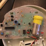
Main parts:
CPU: PIC16LCE625 – One-time programmable 8-bit microcontroller with 2k ROM / 128 byte RAM, 128 byte EEPROM.
MCP6042I/P – Dual Low power (0.6uA) opamp – guard ring attached to pin 7
LM385-1.2 (package marking 385B12) – 1.2V voltage reference with minimum operating current of 15uA.
Noisemaker: Ningbo East Electronics EFM-290ED piezoelectric horn claiming 90dB(A) sound output @ 9V/10mA @ 30cm.
Has GND, main and feedback connection.
Ningbo East Electronics ELB-38 or ELB-74 (?) – 3-terminal inductor (autotransformer) generating a stepped-up AC voltage to drive the horn.
A scattering of bog-standard transistors (2n3904/3906) rounds out the silicon ensemble.
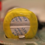
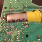
The detector is a large metal cylinder marked with a Kidde part number and has a silica gel (dessicant) package shrink-wrapped to the front of the detection end. The detector is soldered to the board and not replaceable.

Some points of interest:
Idiot resistance: One thing to notice even before taking the unit apart are the little red spring-loaded tabs underneath each battery socket. I couldn’t find anything on the purpose of these in a quick web search, but my guess is they are there to block you from putting the battery door back on with no batteries in, e.g. after pulling them to silence a chirping alarm at 3am, and then forget to put new ones in.
Horn drive: Piezo horns are resonant systems with a very high Q; they must be driven at resonance to produce anywhere near their maximum sound output. However, due to manufacturing tolerances the exact resonant frequency may differ significantly between individual units. Another issue for this device is that piezo horns need comparatively high voltages to operate: this one has a rated voltage of 9V, but can probably go a fair amount higher (>100V drive signals for larger piezo sounders are not uncommon). But, the 3x AA batteries in this device can deliver a maximum of only ~4.5V. The self-resonant oscillator formed by Q2 and L1 efficiently solves both problems. The ‘feedback’ pin connects to a small patch of piezo material on the horn that acts as a sensor, translating deflection to voltage (more or less). Using this as the control signal for a simple oscillator allows it to automatically pull in to the piezo’s resonant frequency. The autotransformer coil, L1, is basically a step-up transformer with one end of its primary and secondary windings tied together and connecting to the 2nd pin. (You can think of it as a single winding with an asymmetric center-tap if you prefer.)
Detector analog frontend: The FR4 material the PCB is made of is a pretty good insulator, but its resistance is not infinite. With sensitive high impedance signals in the tens of Megaohm or more, even the tiny leakage currents across the PCB can induce a measurement error – especially when dust, finger oils from manufacture, other residue and humidity from the air combine on the surface. Notice the exposed silver trace that completely circumscribes the PCB area occupied by the sensor, with its green soldermask covering purposely omitted. This is almost certainly a guard ring intended to intercept such PCB leakage currents before they reach the connection points of the chemical CO sensor. The trace will be attached to a low-impedance circuit node whose voltage is as close to the sensor terminal voltage as possible, minimizing the voltage difference between them, and thus the current that can leak across. The trace is tied to pin 7 of the opamp.

End-of-life-lockout: As mentioned previously, this device is programmed to commit suicide after 7 years. There is no battery backup inside the device, nor any discrete realtime clock or other means of telling the time. How does it know when 7 years have elapsed? The CPU is clocked by a 32.768KHz crystal oscillator, otherwise known just as a “watch crystal” due to their ubiquitous use in watches, clocks and other timekeeping applications. While running the CPU at such a low speed also has certain power advantages relevant to a battery-powered system, this crystal is providing an accurate timebase. Needless to say, it is counting 7 years of power-on time, not wall time (even if it sat on the shelf quite a while, your alarm will not be dead and chirping the moment you remove it from the package). The CPU sports 128 bytes of EEPROM, which are used to store the peak CO reading (over the product’s lifetime or since the last alarm; not sure which) and most likely periodically count down its remaining lifetime. Basic operation of a CO detector is to stick batteries in and forget about it (unexpected powercycles will be infrequent), so the timekeeping can be very coarse, e.g. decrementing a couple-byte EEPROM countdown every time a very long counter rolls over some preprogrammed value.
I pulled the CPU, hooked it up to an ancient PIC programmer and tried dumping the firmware to see exactly how this worked, just in case they had left it unprotected, but no such luck. The code protect fuses are all set and readout attempts return all 0s. The EEPROM in this particular chip is actually implemented as a separate I2C “part”, either on the same die or a separate die copackaged with the CPU die, with the two I2C control pins and a power control line memory-mapped into a register. So there is no access to the EEPROM contents through a PIC programmer either.
Enclosure: At first glance, it’s about what you expect from a low cost consumer product that is designed to be thrown away periodically. There is not a screw to be found anywhere – everything, from the PCB to the enclosure halves themselves, clicks together via little plastic tabs. But wait a minute… hold this up to the light just right, and you can see hand-finishing marks where extra plastic (e.g. overmold) from the injection molding process has been filed or sanded off. On the *inside* of the enclosure, where nobody will see it! And yes, these marks appear to be from work applied to the finished enclosure itself, not the master mold it came from – the sanded portions go slightly in, not out.

Hidden Features: There are a few hidden features suggesting this same PCB, CPU and firmware are used for several models of alarm, including a fancier one. The most obvious is a non-stuffed footprint for another pushbutton switch, marked ‘PEAK’. When pressed, it causes the green test LED to flash a number of times in a row (presumably corresponding to the peak CO level ever measured by this detector – my 2 dead units show 9 and 10 blinks, respectively). Near the center of the board is a non-stuffed 6-pin header, with the outer two being power & ground, and the middle four signals going straight to CPU pins. Scoping these reveals unidirectional SPI signalling on 3 of the pins (CS\, CLK, DATA) that would probably drive an LCD readout on a more expensive version of this detector. Capturing the data in various modes doesn’t produce any obvious pattern (e.g. ASCII, numeric, BCD or raw 7-segment data). Finally, there are two mystery pads on the back of the PCB. Shorting them causes both the alarm and test LEDs to light, and the green LED to produce 5 extremely rapid blinks every few seconds. Doing this does not reset the timer-of-death, clear the PEAK reading or have any other long-term effects that I can ascertain. Both the PEAK switch and mystery jumper noticeably change the data pattern sent to the nonexistent LCD.
BUT… I did find a sequence of inputs that put the detector into some kind of trick mode permanently (persisting across powercycles). I believe the exact sequence of events that triggered it was to have S2 shorted at powerup, then short PEAK once the blinking sequence starts. It’s not clear if S2 must remain shorted during this time or only at powerup. The unit this sequence occurred on is now permanently in a mode where it emits long, repeating rapid blink sequences on the green LED (red lit continuously) and draws some 40mA continuously. The repeating sequence is 1 (pause) 63 (pause) 68 (pause) 24 (pause) 10 (last blink is longer) (pause) 21 (pause) 82 (pause) 82 (pause) 14 (long pause).
Leave a Reply