
So, a friend of a friend recently managed to buy the original Rez, complete with new-in-box Trance Vibrator. But the peripheral didn’t work – it would be detected, but otherwise not do anything. Knowing I had produced a compatible open source version of this hardware, she brought it over for a look. The motor was seized up, probably due to not having spun in over a decade, and easily fixed with a drop of sewing machine oil. But while I had it open, I decided to resolve a longstanding mystery about the device. You know I’m a sucker for LEDs.
Mystery LEDs
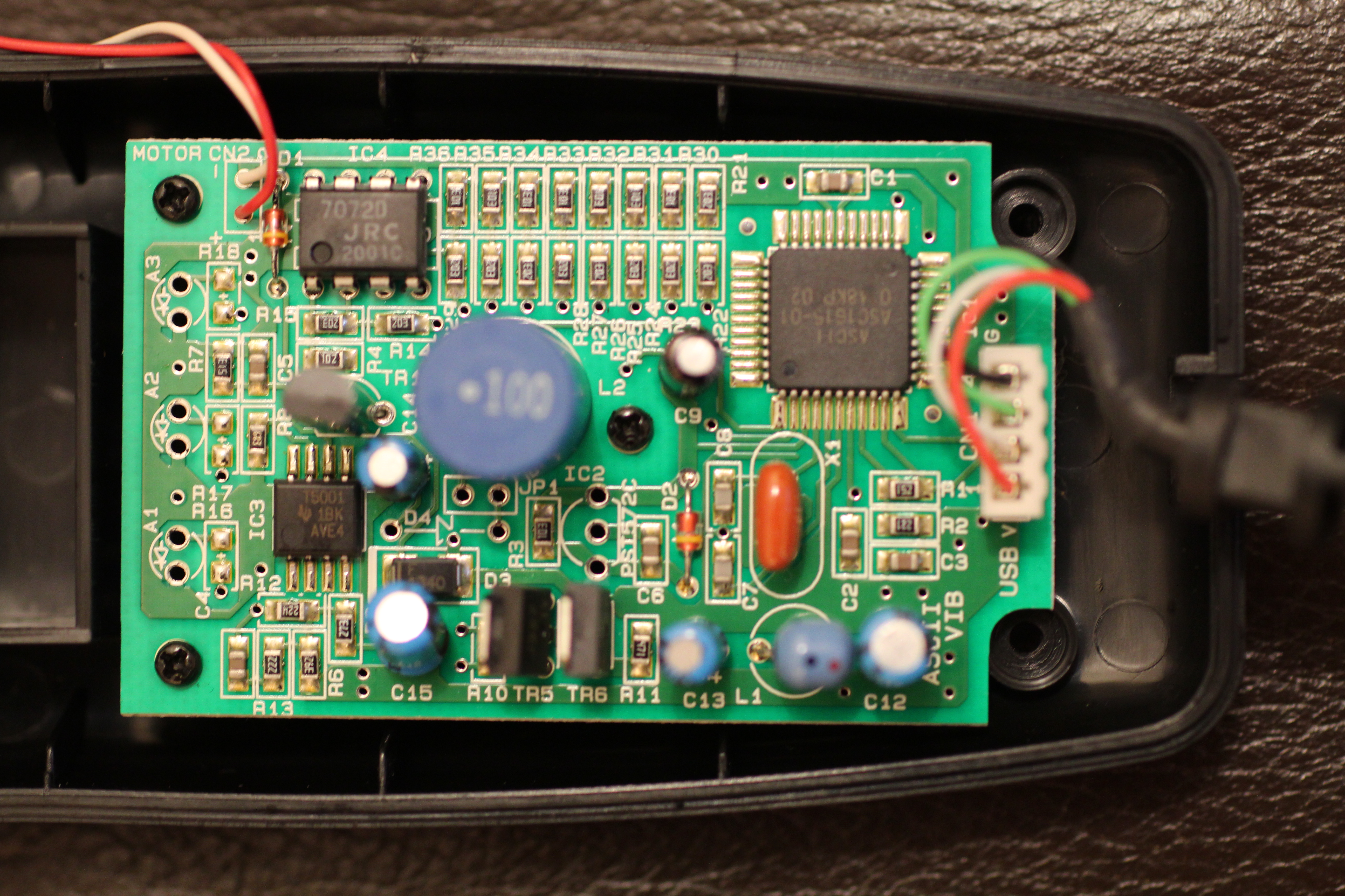
Looking at the PCB reveals footprints for 3 non-placed LEDs and associated current limiting resistors. Facing them on the front side of the case are 3 rectangular pockets of an appropriate size to receive such LEDs, but no openings exposing them to the outside world. (Similar walled structures are used around LEDs in close proximity in other gadgets to block light from the neighboring LEDs.) It’s possible such openings were originally intended to be drilled later… or the mold design was hurriedly changed to remove them, but the pockets themselves remained.
So I stuck some 3mm LEDs there to see what would happen. I assume they were probably meant to be Red/Green/Blue, but I just used the colors I had on hand, along with a trio of 1k 0805 surface-mount resistors.
I don’t have Rez or a PS2, so I fired it up with the test utility I wrote for the Drmn’ Trance Vibrator project. The LEDs light in a changing pattern in response to changes in motor drive level. I wasn’t sure if it was intrinsically tied to motor intensity or some other data, so a quick test was in order. A faithful implementation of the ASCII vibrator’s USB protocol includes some redundant data, which could be omitted without affecting device operation, so I suspected the smoking gun would lie in these extra bytes.
Sure enough, the LEDs can be set arbitrarily via a byte in the USB packet, independently of motor control. The low byte of wIndex, specifically the 3 LSBs, directly set the LED states. The LSB controls “A1” and the next two control “A2” and “A3”, respectively. Although the LEDs can be controlled independently of the motor, the official Rez game always sets the low byte of wIndex equal to the low nibble of the motor power level it is commanding. Observing a USB packet dump of a level playthrough reveals no attempt to drive the LEDs independently. (Since that feature never made it into the released Trance Vibrator itself, it’s not surprising that the game’s developers didn’t agonize over what they could do with it. I’m a little surprised the game passes any data for that byte at all.)
LED control is all-or-nothing. At this point I suspected the high byte of wIndex (always sent as 0x03) might control intensity, but fuzzing around with this value or the others (e.g. the bRequest of 0x00) has no effect.
Here is a quick Python script demonstrating blinking the trance vibe LEDs.
And a video of them in action:
But why were the LEDs removed?
The first answer that may spring to mind is cost cutting… but it doesn’t make too much sense at first, because LEDs are pretty cheap. Or are they? Simply poking them out of holes the front of the enclosure would wreck the watertightness of the enclosure without some kind of gaskets, sealants, or clear windows to cover the openings. Even though the game’s creator says the device was not intended to be sexual, if you put humans near something that vibrates, the first thing they will do is stick it on their fun bits. No. Exceptions. Having openings in an ultimately line-powered device meant to be used that close to the body might have opened them up to regulatory headaches, e.g. medical-grade power supply isolation, and might just not have been a good idea overall.

The most logical reason for the removal of the LEDs, though, is that they just wouldn’t really work. Unless you are a contortionist, there are very few ways one could use this device as intended and still have them in your line of sight. I suppose it’s possible they were meant to work as a very early Ambilight-type system if played in a darkened room, but you’d still need some pretty bright LEDs and a pretty small room. It also wouldn’t work from a shirt or pants pocket, or with the protective cover on.
The rest of the circuit
Operationally, the circuit inside is actually pretty close to Drmn’ Trance Vibe, although approached in a very circuitous way. Both generate a PWM signal that controls a transistor to modulate the motor speed. In the ASCII vibrator though, rather than directly generate the PWM signal from the microcontroller, it instead outputs an 8-bit value via I/O pins to a crude DAC (R-2R ladder), which feeds into an opamp (buffer?) and eventually a TL5001 discrete PWM generator. This drives a transistor, which may in turn drive another identical transistor to drive the motor. I have no idea what the 3rd large transistor, next to the PWM generator, is for – I didn’t feel like digging to that level of detail on borrowed hardware that I had to return in working condition :-)
There is a non-stuffed mystery jumper near the large inductor at center, which receives (or would) its output from a similarly non-stuffed diode, and leads to an I/O pin on the microcontroller. In my quick testing, this appeared to be an analog signal which remained at or near ground through all normal operation. I suspect it connects to the overcurrent signal on the PWM generator, and would cause the CPU to halt the motor if tripped, but don’t bet the farm on this. It doesn’t appear to invoke a bootloader, diagnostic mode or anything similarly interesting.
Here are hi-res pics of the PCB, if anyone is interested:

Leave a Reply