This information is common to all versions and can be found on the main Resources page.
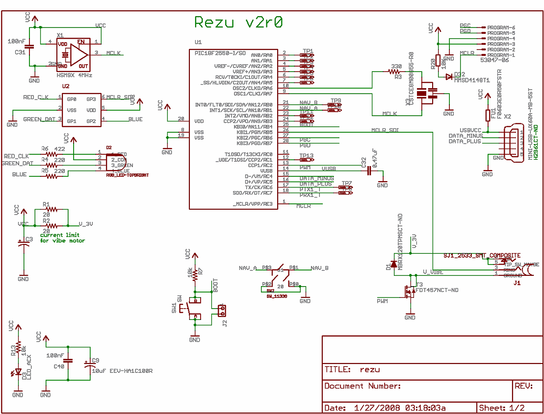
V2 features modular connections for both the USB and vibrator connections, so wiring is no longer necessary. The on-board connectors are:
USB end: Mini-B Receptacle (Hirose p/n: UX60A-MB-5ST, Digikey p/n: H2961-ND)


Drmn' Vibe V2 includes a built-in bootloader allowing custom firmware to be easily loaded onto the device without special tools. 99% of users will never have reason to use this feature, but it's there. This is mostly good for writing your own extensions to the protocol, or repurposing the hardware as a protocol debugger, or custom USB peripheral driving the 'hidden' I/O port or custom hardware soldered to the PIC pins, etc.
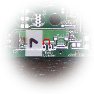
The bootloader is invoked by having the jumper pads marked "Boot Loader" shorted (e.g. with a pair of tweezers, or solder pins and a removable jumper) while plugging the device in. Instead of the Drmn' Trance Vibe (VID 0x0b49 and PID 0x064f), it will enumerate as the Microchip USB Bootloader Client (VID 0x04d8 PID 0x000B).

Drmn' Vibe firmware and source code - PIC18F2x50 assembler relocated to 0x0800.
This is essentially Bradley Minch's Bulk driver for PIC18F2x50/4x50 with the Trance Vibe handling code and some debug stuff chucked in. It can be assembled using the free Microchip MPLAB IDE / MPASM Assembler.
Drmn' Vibe bootloader and source code - PIC18F2x50 C starting at 0x0000.
This is Microchip's USB Bootloader v1.0 modified to enter bootloader mode depending on the state of the BOOT switch, and with some unnecessary stuff trimmed so that it will still fit into the 2k Boot Block (0x0000 ~ 0x0800) using the free Student Edition of the Microchip C18 Compiler (i.e. optimizations disabled).
This file also includes PC programs for Linux and Windows to communicate with the bootloader firmware.
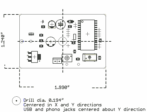
EAGLE schematic and printed circuit board design files

Back to the main Resource page
Back to the Trance Vibrator project page!
Email: drmn4ea @ that google-y moogley mail place