This weekend I got some parts in and put together a preliminary placement head for my open-source pick ‘n place project. My requirements are that it be buildable with off-the-shelf parts (ideally same-source, to save on shipping) and no special equipment, allow +/-180 degree rotation while maintaining an undisturbed vacuum, and support interchanging of the “tools” (vacuum needles). All that’s really needed to build this are the discrete parts shown, a bit of drillable plastic (e.g. Delrin) for the base material, and a drill. A drill press would be handy (a CNC mill *really* handy, and not such an out-there thing to have considering you are probably retrofitting this onto one).
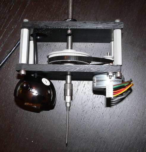
This head consists of a hollow rotary shaft with a Luer lock fitting on one end, right-angle flexible tubing barb on the other end, and a large toothbelt (notched belt, timing belt) gear in between. The shaft is held in place but allowed to rotate by a pair of bearings, and the rotation is provided by a small stepper motor at the other end of the toothbelt. The gear ratio is approximately 5.2:1, providing a rotational resolution of about 0.35 degrees/step with a common 200 step/rev stepper motor (if no microstepping is used). Finally, just to the left of it is a 1024×768 Webcam with manually adjustable focus and a ring of built-in LEDs for lighting. The webcam mounting is definitely not ideal, given the camera’s weird eyeball-like shape. Tentative plan is to lash it down with some string, align it nicely with respect to the CNC table, then backfill the opening the camera’s butt sits in with epoxy.
The hardest part was finding a combination of parts that would all fit together nicely. Currently, the fits are mostly exact to “pretty damn good”, but a bit of adhesive is needed to join them permanently.
Parts List
Unless otherwise noted, all of these parts were sourced from Small Parts Inc. in the US due to the large selection and an actually competent parametric search engine, which was a great help in finding combinations of mutually-fittable parts. Accordingly, measures are in Imperial unless noted otherwise (that’s just how they come here).
| Partnumber | Desc. |
| 3002DSTNTG18 | Nice Ball Bearing 3002DS, .250″ bore x .6875″ OD x .250″ width |
| BFM-250-P | Mounted sleeve bearing, .250″ ID, 1 17/32 center-to-center bolt spacing |
| B00137SITY | Steel tubing, 1/4″ OD .152 ID, 12″ long |
| 40DP-14/S-01 | Timing Belt Pulley Delrin, 0.0816 Pitch, 40DP, .350″ Diameter, 1/8″ Bore, For up to 1/4″ Wide Belt, 14 teeth |
| 40DP-70/S-01 | Timing Belt Pulley Delrin, 0.0816 Pitch, 40DP, 1.806″ Diameter, 1/4″ Bore, For up to 1/4″ Wide Belt, 70 teeth |
| TB188-090-01 | Timing Belt Urethane/Polyester, Single-Sided, 0.0816″ Pitch, 0.1875″ Wide x 7.3440″ Long, 90 Teeth |
| LCX-LC005 | Male Luer Lock to tubing adapter, .145″ OD hose barb (mates well enough with .152″ ID steel tubing) |
| F1-EL001 | Elbow Connector , Classic Barbs for 3/32″ ID Tubing, .145″ OD |
| HSTA-08-24-10 | 1.5″ aluminum standoffs, 8-32 thread |
| B00137UP68 (Optional) | 11ga Steel Tubing, .120″OD, .094″ID (for mating 2mm shaft stepper motors, if used, to the 1/8″ pulley |
Misc. Parts
2x 2″ x 4.5″, 1/4″ thick pieces of Delrin or similar
4x 1/2″, #4-40 bolts and nuts (assuming 2 bolts for stepper motor)
4x 1/2″, #8-32 bolts for standoffs
1x Webcam, manual focus, hi-res and builtin lighting strongly recommended
1x 3mm shaft stepper motor*
1x Method of attaching to your mill – a bit of aluminum angle bracket, or a dovetail, etc., depending on your mill.
1x 3-way air solenoid valve
1x Vacuum source (see here for a cheap one)
Air tubing and appropriate couplings to your solenoid valve. The head’s air path terminates in a 3/32″ hose barb, so you’ll want a 3/32″ to (whatever) barb adapter, or a 3/32 that screws directly into your solenoid. Those using metric are on your own :-) but will probably have an easier time of it anyway.
* The timing pulleys and stepper motors only come in a handful of diameters (imperial for the pulleys and usually metric for the small motors), so a 3mm (.118″) motor onto a .125″ ID pulley was the closest I could come up with in a reasonable amount of effort. Any small, el-cheapo permanent magnet (“tin can”) stepper motor should work here, but sourcing it may be annoying. Off-the-shelf 3mm-shaft motors I found are Jameco’s ValuePro 42BY48H08, Anaheim Automation’s TSM42 series, and Portescap’s 42/44 series e.g. 42×048 and 42S100. This surplus stepper is also worth a look, but you’ll have to remove a pre-attached plastic(?) gearhead. Beware, many of these smaller motors are 7.5deg/step, so even with the gear reduction, you will probably want to look at microstepping them to ensure adequate rotational resolution. Also, most of the companies selling them have no online click-and-buy ordering; you’ll have to phone up a salesdouche at the least, hope that you are worth their time to buy One Lousy Motor, and possibly haggle (“Request a Quote”). How companies that don’t know what their product costs stay in business is beyond me, but that’s a rant for another day.
If you want to skip that hassle, I’ve taken an alternative approach and simply bodged a surplus 2mm-shaft motor up to a 3mm shaft by gluing a short piece of thicker steel tubing onto the existing shaft (see partlist).
Design Files
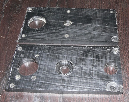
CamBam drawings with machining operations for the top and bottom plates. The machining ops assume 1/4″ thick plastic, 1/8″ endmill for most cuts, and .166″ (#19) drill for the #8-32 bolt holes into the standoffs. It’s designed for the Cubeternet webcam (or equivalent eyeball-cam) and a stepper motor with 42mm center-to-center mounting holes. You can get the free CamBam at http://www.cambam.co.uk/.
Note, I made some small improvements to these files after the above prototype was carved, so what you see in the file will not match it exactly. In particular, the standoffs were moved to more optimal places and a feature has been added allowing the motor to be slid to remove any slack in the belt.
Assembly
The assembly should be pretty self-explanatory. One bearing on each of the Delrin plates (inset the ball bearing if you can; otherwise gluing it down should be fine). The hollow shaft goes thru the bearings, Luer adapter and hose barb go on either end (use adhesive, just don’t clog the air path with it). The motor shaft center should sit just a hair (50-100 mils?) over 1.75″ from the hollow shaft. On mine, an online calculator produced the 1.75 figure, but the belt turned out to be a bit loose once built this way. If possible, make an elongated hole for one of the motor screws so the motor position can be adjusted to tension the belt. You could probably also insert a peg somewhere in the belt path to push it inward and take up the slack. With the camera focus set such that the largest part you will ever populate can fit in-frame, find the resulting camera height (distance from part) and set the depth of the shaft so that the camera is “in focus” maybe an inch or two above the placement position (i.e. with the needle touching the board). This will allow the head to focus on parts without touching the needle down.
For my build, I used instant glue to attach the Luer adapter to the needle shaft, and hot-melt glue to tack down the large pulley and hose barb. None of these parts should be seeing significant force; if they are, you’re Doing It Wrong and the hot glue should hopefully break loose before something more important does. Using a non-permanent adhesive for the hose barb and pulley also allows this assembly to be disassembled later if needed. The shaft itself is free-floating and the large pulley rests against the ball bearing due to gravity. This will prevent damage due to crashing the needle into the table or too-tall part, but if you experience problems with the shaft riding up on its own, try adding a bit of extra weight or put a dab of adhesive where the shaft passes through the lower bearing.
Suggested “v2” improvements
–Move air valve (if/when one is specified) onto head to minimize air volume between valve and head. Needed? (may be beneficial for reversed aquarium pumps or other weak vacuum sources)
–Bump detect: rather than firmly adhere the shaft into the bearing, allow it to float up and down, normally resting by gravity with the large pulley against the ball bearing. Place a contact switch just above the pulley: if the head/part contacts the surface with more than minimal force (enough to lift the shaft), contact switch is triggered. This could be used to halt the machine if a bump was not expected. If the switch’s trigger position is reliable enough, it could be used intentionally to automatically determine component heights.
–Probe function: There is a conductive metal path from the needlepoint all the way up to and including the bearing outer race, so it would be easy to touch a contact here and use the needle to probe for any conductive objects (e.g. find the tabletop if it is metal, or some capacitive shenanigans for PCBs/etc.). Useful?
Leave a Reply