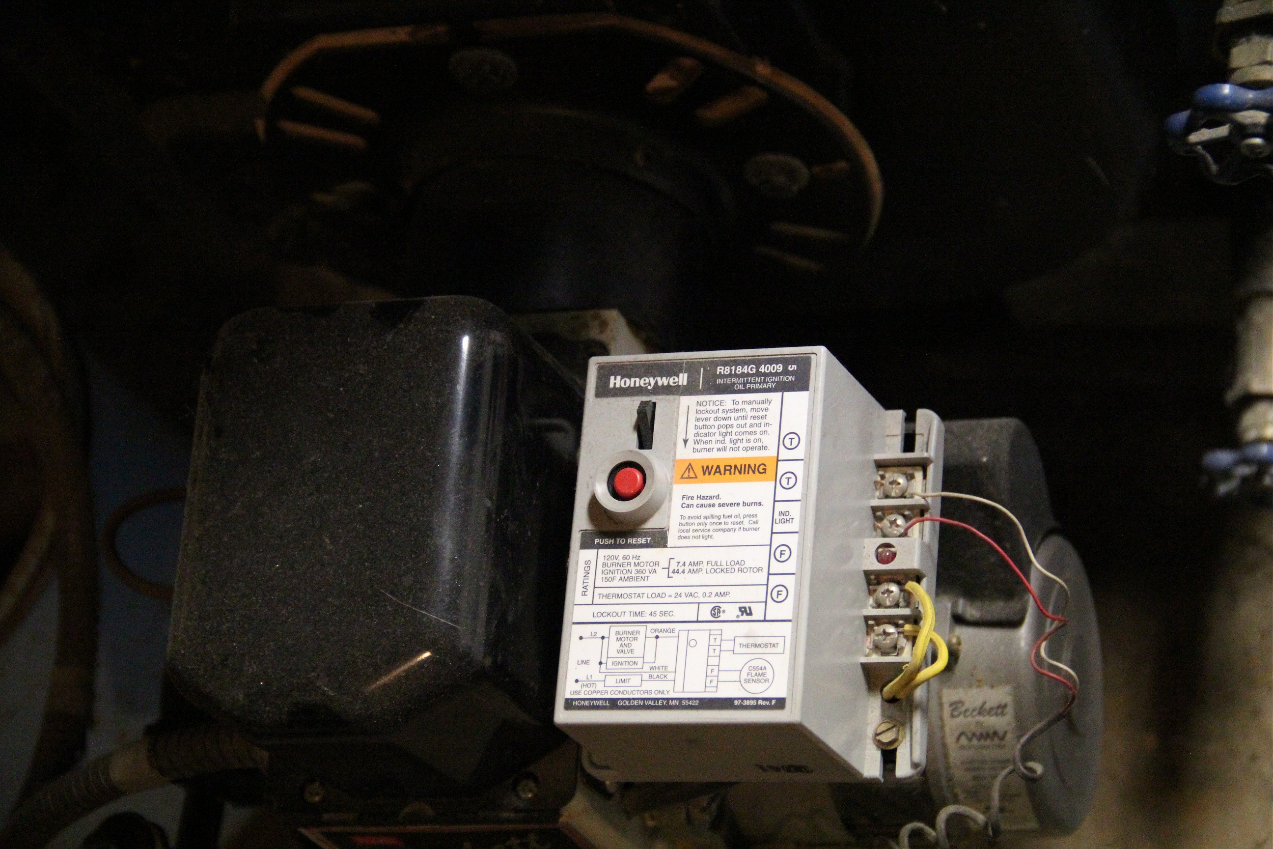
Its official designation is “R8184 Intermittent Ignition Oil Primary”.
“But Tiiiim! That sounds booooorrrring. Why this thing, and not one of those fancy cloud-enabled thermostats containing more RAM than the desktop computer you had in college and not less than five processors capable of running Angry Birds at a playable framerate?”
Yes, excitement-wise this one sounds right up there with having your toenails waxed, but there are a few interesting bits regardless. Also, I have a broken one sitting in my basement right now, and what do we do with broken gadgets?…
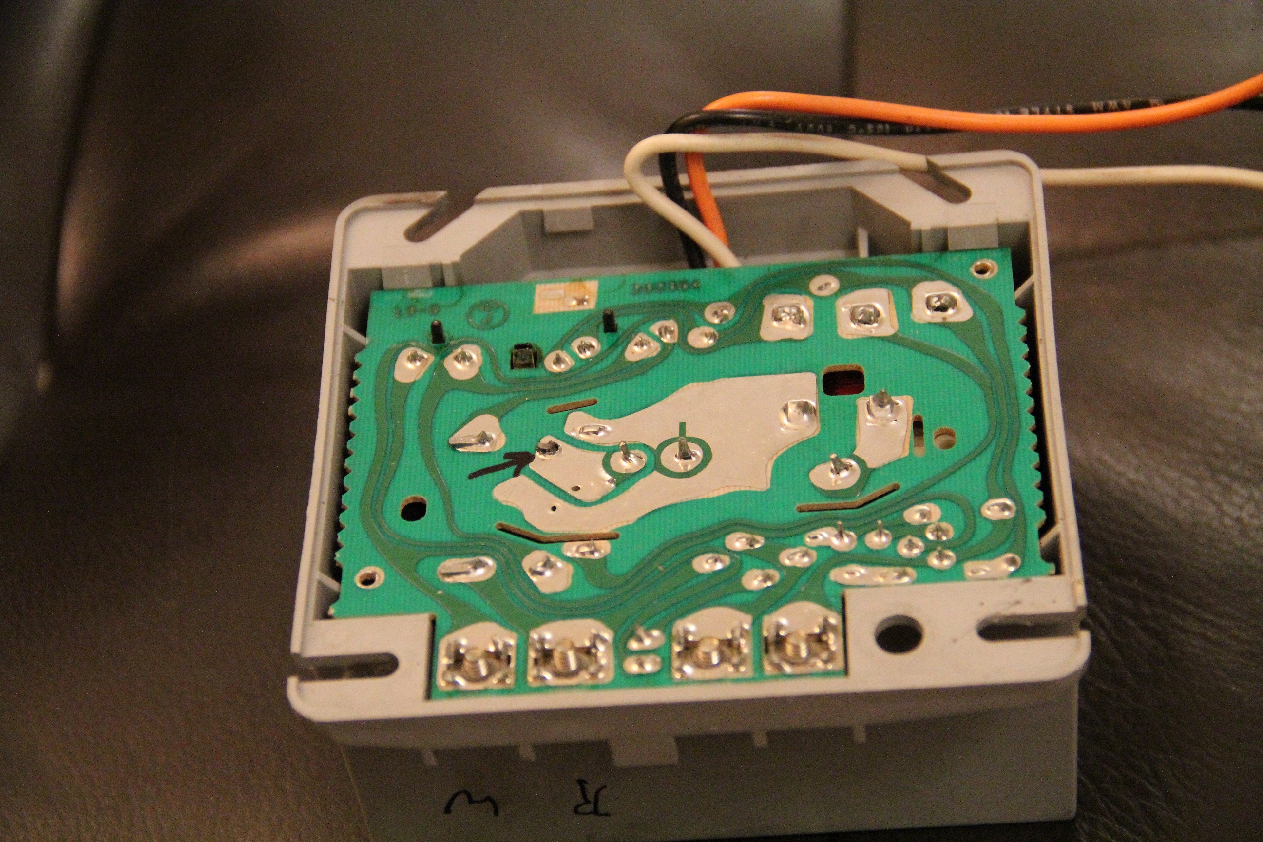
Here is the underside showing the PCB. This should give some sense as to the age of this design. These curvacious traces are something you just don’t see in the era of computer-aided PCB design. This board may very well have been laid out literally by hand, the master trace pattern drawn in magic marker. Speaking of which, I drew an arrow in marker pointing to the likely culprit for this unit’s failure: a cold solder joint on one of the relay terminals, specifically, the one that energizes the orange wire leading to the burner and motor. You can also see some strategic cuts in the board itself, providing a physical air gap to isolate the low-voltage stuff from the line-powered sections nearby.

Here is the topside. There’s really nothing much to it! You can probably take a stab at how this all works just by inspection, but in case not, Honeywell provides the actual schematic on their website.
The fat transformer at top-left steps the 120VAC from the line down to around 24VAC to drive its own circuitry and the thermostat (red and white wire normally connected to the “T” terminals). I peeled back the tape on the primary winding a bit so you can see the difference in wire diameter, allowing for many more turns on the primary side. Without documentation or proper test equipment, you could use this to visually determine its function as a step-down transformer and maybe even make a loose guesstimate of the turns ratio.

Kitty-corner from this transformer is a big honkin’ relay, armed with a similarly fat bundle of wire. This coil is powered right from the AC off the transformer; notice the large metal weight clamped to the top end of the part that actually moves. I suspect this is to provide added inertia to keep the contactor in-place and prevent buzzing during the low periods in the AC cycle where the magnetic force ordinarily holding it drops out. Energizing this relay closes two separate pairs of contacts; one (with the cold solder joint) powers up the boiler via the orange wire, and the other completes the circuit (transformer center tap, or ~12VAC) for the safety lockout logic, which I’ll get to in a moment.
In an oil burning boiler, turning on the boiler engages a large motor that both blows air into the combustion chamber and forces oil through an atomizing nozzle. The oil is ignited by a spark plug of sorts, formed by a high voltage transformer and a conductor near the nozzle. Home heating oil is otherwise known as diesel fuel. Needless to say, you want this atomized fuel to burn away in a quick and controlled way, not let large quantities of it accumulate and then go up suddenly.
To prevent your basement turning into a Super Mario Bros. boss level if the fuel doesn’t ignite in a timely fashion, there is a “flame sensor” (photocell) and lockout timer built in. The label on the front of the unit specifies a lockout time of 45 seconds. As you probably noticed, there are no microcontrollers, quartz crystals, counters or any other obvious timing devices on this board, so how does this work?
The answer may wow you, either with its ghetto-ness or its ingenious simplicity. Much like the electric stove guts described in an earlier post, the timer is thermal. The top-right component contains a heating element attached to a bimetallic strip, which in turn connects to some contacts and a mechanical latch. This is attached to the bit of circuitry at the bottom-left, which connects to the photocell (flame sensor) normally connected at the ‘F’ terminals. For the grisly details, look at the schematic linked above. Ordinarily, when the thermostat is on 24VAC flows through R1 and R2 to the “bilateral switch” (there’s a symbol and part you don’t see everyday), which trips the TRIAC and ultimately begins warming the heating element, eventually curling the metallic strip inside the lockout mechanism enough to trip and cut power to the boiler. Note, the schematic shows the gate of the “bilateral switch” not connected to anything, but in reality it is shorted back to the first terminal (at R2), turning this device into basically a voltage threshold detector. Light falling on the sensor lowers its resistance from near-infinite down to the k-Ohm range or less, forming a resistor divider with R1. This lowers the voltage at the bilateral switch below its turn-on threshold, cutting power to the heating element before it trips the lockout.
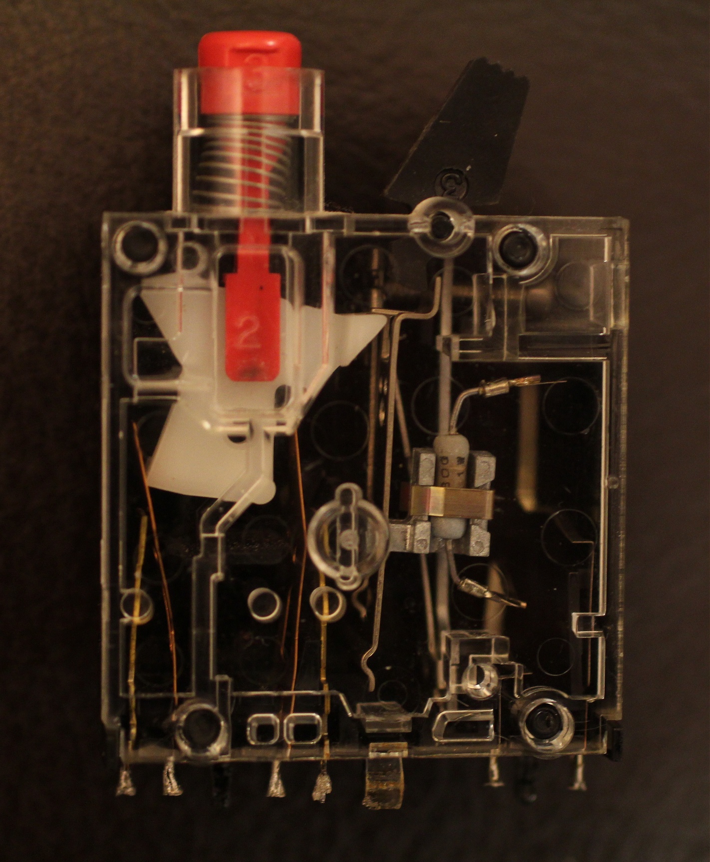
A look through the clear plastic case of this device shows the heating element is an ordinary 1W flameproof resistor. A metal slug, no doubt carefully sized to provide the right thermal inertia for the desired lockout time, is clamped around it. On the side of the device is an access hole for a setscrew, which applies pressure to a spring-loaded plate behind the bimetallic element. This most likely sets the initial position/tension of the strip against the pushbutton latch, and so allows fine-tuning the trip time.
Here is a video of the mechanism in action.
If the previous TTIA installment was any indication, the burning question is how much the thing cost to manufacture. As before, the off-the-shelf parts are pretty cheap but the presence of complex custom parts makes it hard to pin down a number. A comparable step-down transformer can be had for about $5-8 bucks on Digikey. The discretes would run probably another buck total, and give another $3-5 bucks for wiring, the solder-on screw terminals and the blank PCB itself. The transformer is a bit harder – it’s a custom Honeywell part and can’t be sourced off the shelf – but comparably sized transformers might run in the $20 range in onesies. Now for that lockout switch assembly, that’s a real piece of work. Not heavy on any expensive metals, but plenty of NRE sunk into this part, and plenty of mechanical parts to assemble (possibly some or all by hand). I’ll pull a $15 out of my ass for that component.
Leave a Reply