One of these devices appeared in a large shipment of temperature-sensitive raw materials at my work, amid a pile of dry ice chips. While I don’t know the MSRP or actual retail price of this gadget, the shipper packs one in with every order and tacks on $60-70 for it as a line-item; nonreturnable as far as I know.
So, we can’t return it and we can’t read it out, so what do we do?
I think you know what we do :p
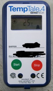
The device is aimed at exactly this application – telling if your temperature-sensitive stuff stayed within a defined temperature band during all phases of shipping and handling. With timestamps, you could probably tell exactly which party in the shipment chain screwed the pooch. There is a fancy term for this kind of tracking – cold chain certification.
As far as interfaces go, it doesn’t get much more simple. A button to start logging, a button to stop logging, a simple LCD display, and a couple blanks to enter a shipper’s name and the PO# of the shipment. The current temperature and recording status (started / stopped) is displayed on the LCD. If the temperature went outside the allowed band while recording, an alarm symbol (bell) also appears. A pair of LEDs exposed through the front panel allow the device to be configured and recorded data to be read out to a PC via an optical doohicky (more on this later).
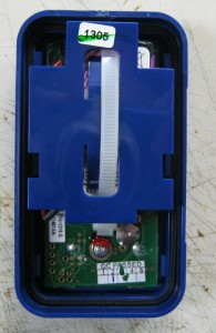
The enclosure is a basic 2-piece sandwich, with the half-thickness (.031″) PCB fixed into the front by 3 screws. A separate plastic ‘cage’ holds the battery pack in place; fingers on the backside clip around the edges of the PCB. The entire weight of the battery pack – and impact loads it imparts during rough shipping – are borne solely by the PCB and ultimately those 3 screw points. They might not anticipate extremely rough shipping for cold-chain cargoes (although a broken logger could be spun as a rough-shipping-detection “feature”).
On the plus side, note the O-ring ensuring a water-resistant seal between the case halves. Any other case openings are covered by the front overlay “sticker”, eliminating any fluid intrusion paths.
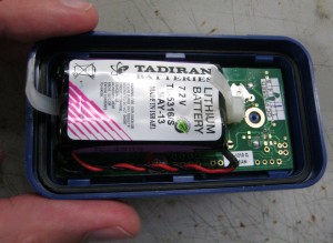
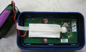
The battery pack is Zip-tied to the plastic “cage”, although not to the PCB or any part of the case. A piece of foamy double-stick tape helps hold and cushion the battery pack where it sits against the PCB. This and the overlay sticker on the front suggest this device is intended for enforcing low temperatures. High-temperature overlays and even double-stick tape exist, but it’s pretty fancy stuff. This tape isn’t fancy.
The battery pack consists of two series-connected Tadiran lithium primary cells (AA size), with a nominal 7.2V output. Now, in an industry that is constantly pushing toward ever lower voltages to reduce power consumption, this is weird! Especially for a gadget that needs to go a long time without a battery change. A single 3.6V cell will easily power a 1.8-3.3V device, and maintain this output voltage until nearly depleted. Some wild guesses at the reason behind the unusually high voltage:
1) High-current operation at very low temperatures. This shouldn’t be an issue during normal operation (just datalogging should use very little current on average), but if someone wanted to read it out over the optical interface in the Arctic, it may be another story. This may provide extra headroom against the inevitable cold-battery voltage sags that would occur as the transmit LED fires.
2) Voltage-happy LCD? Some LCDs require a higher voltage such as this to operate (usually generated by an onboard charge pump circuit), but these are typically graphical matrix LCDs (many independent rows/columns) – the rows/cols are typically energized one at a time, and to refresh the entire display faster than the eye can perceive flicker, each one is on for only a very short time – higher voltages help them reach their final dark/light state within that time and retain it until the next refresh. I can’t imagine this little segment LCD having such a requirement.
3) They needed 2 batteries to get the milliamp-hours up regadless, and wiring them in series was easier/cheaper (no worries about cell balancing). This is not an ideal way to get more mAh (increasing resistive losses in the series-connected pair, and conversion losses in any regulator, especially linear/LDO), but I suppose it works well-enough, and the price is right.
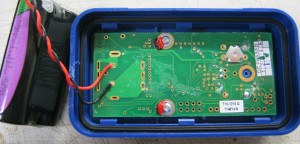
With the battery pack out of the way, we can see the bottom side of the PCB. Not much there! A couple things to note though:
1) A secret button hidden inside the device. As it turns out, this button resets/clears the device for reuse. The entire LCD will blink every segment for a couple minutes, then the device is factory-fresh again (probably).
2) No components apart from the secret button, but a fair number of empty pads (non-stuffed components).
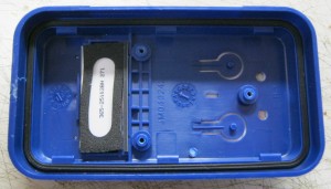
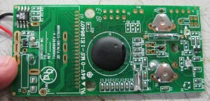
Finally, we get to the topside of the PCB, the actual meat of the device! Erm, wait a minute, where’s all the meat?
The $70 pricetag notwithstanding, it should be becoming clear that this device is cheap-cheap-cheap to make. The bill of materials consists mainly of a few pushbuttons, a small handful of discretes and a glob-top MCU/ASIC. The segment LCD and an EEPROM in the top-left of the photo (a note on the manufacturer’s web site says it could be 2KB or even a whopping 16KB of storage) complete the ensemble. I have to snicker a bit about that after testing a 32GByte uSD card in my own day-job datalogger design the same day, but again, this device is designed to be throwaway cheap, and 640k (ahem, 16k) ought to be enough for anybody – for temperature data, anyway. (The astute reader will see “32K” stamped on the chip; either a clever misdirection or these loggers have grown more spacious than the web site lets on.)
Some notable points:
1) The temperature sensing element appears to be a simple RTD – no thermocouple or even brand-name digital sensor, but probably accurate enough.
2) The glass tube designated S3 is a magnetic reed switch. This almost certainly is used to trigger entry into the download/configure mode, either with a magnetic wand or a magnet built into a monolithic reader device that aligns to the LEDs.
3) The LCD is affixed to the top shell, not the PCB, and contact is made by an elastomer strip (zebra strip). Don’t lose this!
4) The neat row of capacitors at the bottom of the photo (C2, C3, C10 ~ 13) are probably part of a charge pump circuit for the LCD. There goes that theory about the battery voltage.
5) As with the bottom side, note the prevalence of non-stuffed component pads. Aside from a good handful of discretes, there are spots that appear to accept a second RTD temperature sensor and a humidity sensor. Most likely, this same board and ASIC become the “TempTale4 Humidity” with the addition of these components.
6) Besides the holes for extra sensors, pay particular attention to the two – two! – sets of non-stuffed headers (J1, J2). The latter pins directly into the globtop, suggesting the likely possibility of an in-circuit programming header (or even JTAG, holiest of holy grails).
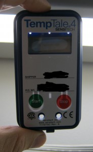
In this final photo, you can see the shell cutouts as they relate to the overlay sticker. The temperature sensor normally sits in the small notch in the middle, leaving only the thin bit of sticker between the sensor and the outside environment.
Leave a Reply