This is a free (open source) Python script for creating feeder sprockets for e.g. perforated tape or film advance. I wrote it for myself to generate SMD tape-and-reel feed sprockets, but it might also be useful for making replacement sprockets for 8/16/35mm film, microfilm and paper-tape systems whose original reader hardware no longer exists or is difficult to find replacement parts for. The output is a .DXF template suitable for laser cutting, 3D printing or CNC machining. “Documentation” below, but it should be pretty self-explanatory. It should work with any modern version of Python (tested on 2.6).
Sprocket design goals / differences from other sprocket types
The drive sprocket’s dimensions are specified mainly by the number of teeth, width (or diameter) of the sprocket holes, and the pitch (distance between sprocket hole centers). The tape is usually advanced either tangentally to the sprocket, or partially wrapped around the sprocket. Thus the distance between the outside edges of any two teeth at any point, either tangent to the sprocket or along the circumference of the sprocket, should never exceed the distance between the outer edges of any two sprocket holes (the taper of the teeth is computed to counteract the radial splay of the teeth). Additionally, a landing area (flank) is cut at the base of the teeth matching the thickness of the tape, giving it a place to ‘catch’ when pressed against the sprocket’s inner diameter. Unlike e.g. roller chain sprockets or spur gears, no undercut (cuts below the inner diameter) is provided for rollers or a mating gear’s teeth, and no special geometry is needed along the sides of the teeth.
Some Terminology:
Pitch: The center-to-center distance between sprocket holes, and thus the sprocket teeth.
Tooth Face: The tapered portion of the tooth. In this application, the tooth taper is calculated to smoothly slide into the sprocket holes as the sprocket rotates.
Tooth Flank: The ‘upright’ (or slightly concave) base of the tooth. In this application, it should be the same height as (or slightly taller than) the tape thickness so that the tape sprockets rest fully within the flank.
Tooth Land: This is the surface left if the tip of the tooth has been blunted or “cut off”. This might be done to fit the sprocket into a particular diameter. I’m an EE; I don’t know what other dis/advantages pointy vs. blunted teeth would have in this application.

Basic usage:
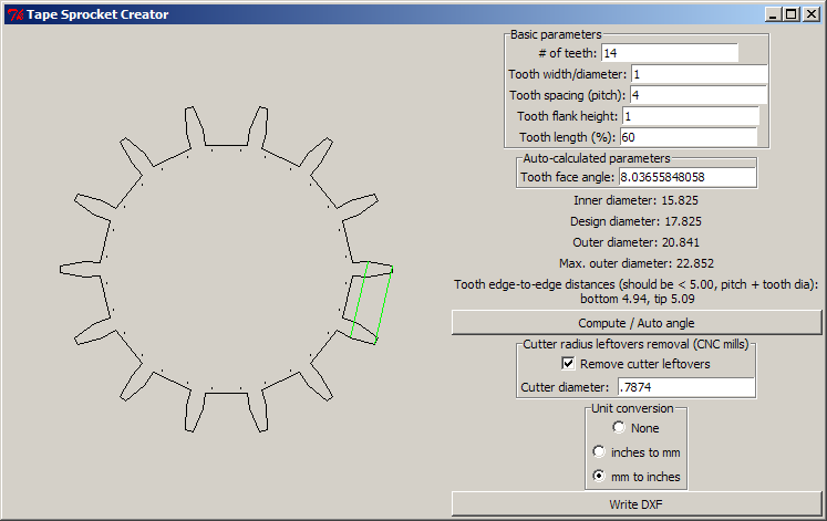
Fill in all the values called for in ‘Basic Parameters’. Aside from angles, which are in degrees, use any unit of measurement you prefer (inch/mm/etc.), as long as it is consistent; output will be in the same units. If you desire a specific tooth taper angle, enter it, otherwise just press “Compute / auto angle” to suggest an angle and generate the sprocket.
Mostly, the pitch and sprocket hole width are dictated by the tape to be fed, and also drive the important diameters. You can get closer to a desired sprocket diameter by adjusting the number of teeth. The important diameters are:
Inner diameter: This is the diameter at the base of the teeth, where the bottom of the tape rests.
“Design diameter”: This is the most important diameter as far as the program is concerned, and is fully dictated by the pitch and number of teeth. The design diameter is the diameter at the top of the tooth flanks, which is the top of the tape. You could also think of this as the outside diameter of the tape if wrapped around the sprocket.
Outer diameter: This is the diameter at the tips of the teeth. By playing with the tooth angle and cutting off the tips (tooth length %), there is some leeway to constrain the outer diameter to fit the available space.
Note that the angle auto-suggest feature is currently broken (will return incorrect results). It will (usually) calculate an angle that will allow the tape to *wrap around* the sprocket at any radius from the base of the teeth, but what you really want is the tape to fit at an arbitrary angle across the teeth (specifically, the outer edges of whatever teeth it intersects while tangent to the sprocket should not exceed the outsides of the sprocket holes). For now you might have to cut a few gears and experiment, or just set the angle arbitrarily high.
Extra Options:
If you will be cutting out the sprocket on a CNC mill, outside pocketing will leave some material at the base of each tooth flank due to the diameter of the round cutter. Enabling ‘Remove cutter leftovers’ and entering the cutter diameter will add DXF points (drill hits) near the tooth edges to remove this material. Users of other fabrication methods can probably ignore this option.
If designing a sprocket in one measurement system for use in another, you can optionally select a unit conversion to be applied when writing out the DXF file. E.g. if your tape is specced in mm but your CAD/CAM software expects inches, select ‘mm to inches’ before saving the DXF.
CAVEATS:
I wrote this to solve a very specific need for one of my own projects; so very little time and debugging went into it. There is no idiot-checking. Expect errors or bizarre output if you leave necessary fields blank, mix & match units (inch/mm) arbitrarily, enter a negative number of teeth or any other physically impossible geometry. Even if you do everything correctly, there is no guarantee the output will be correct or meet your needs. Please check the results very carefully before you lay out any $$$ to have anything professionally made by a fabrication service!
Right now the arc between teeth is output as a straight line, not an arc or series of tiny lines approximating one. This should not be a huge problem for a reasonable number of teeth, but something to be aware of.
Other notes:
“Auto angle” calculation is only done if the angle field is blank: if there is a number there (including a previous auto-calculation), it will be left alone. If you have changed any parameters and want to redo “auto angle”, please delete the contents of this box.
The sprocket image shown in the program window is not to scale – it is automatically scaled to fit inside the window. It is not unusual for the sprocket to appear to change size dramatically when parameters are modified.
Square Pegs and Round Holes:
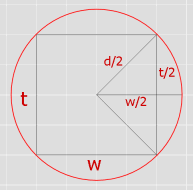
Unless you have some fancy software sweeping the sprocket teeth into 3D, you are probably making a flat gear out of flat stock, and it will have flat edges. If the sprocket holes are round, the tooth edges will contact somewhere earlier than the outside diameter of the hole, and so may need to be tweaked – especially if the material is thick relative to the holes. (See the diagram below for an exaggerated example.) Use this formula to calculate the effective tooth width that will exactly fit the hole:
w = sqrt(d^2 – t^2)
where d is the sprocket hole diameter and t is the stock thickness.
Leave a Reply