My day-job employer makes fancy piezoelectric actuators. Not long ago I was asked out of the blue: “Hey, the Haptics Symposium is in less than 2 weeks… It’s in Houston, TX. Want to go?”
“*looks out window at yet more falling snow* Hell yeah.”
“Oh yeah, and we’re going to need some demos so…”
Of course, I had no shortage of regularly scheduled urgent worky stuff to do, so any demos had to be done with some haste. In the end I got not-one-but-two cheesy demos going, one of which didn’t even break during the show! In addition, my newest coworker put together an incredibly sweet haptic texture-rendering demo, but I’m sure he’s writing it up on his own blog as I speak :p
Super cheesy heightfield mouse
One of the fun things about piezoelectric bimorphs is that, unlike coin motors, LRAs and voice coil drivers, they can be deflected statically. So it’s possible to set and hold arbitrary linear positions. With this in mind, I scavenged an old ball mouse from the IT junkpile, removed the PS/2 cable and ball, and hacked it up so that the left mouse button now raises and lowers in response to the brightness of the surface directly beneath it. An arbitrary grayscale image placed under the mouse now becomes a tactile experience, felt rather than seen.
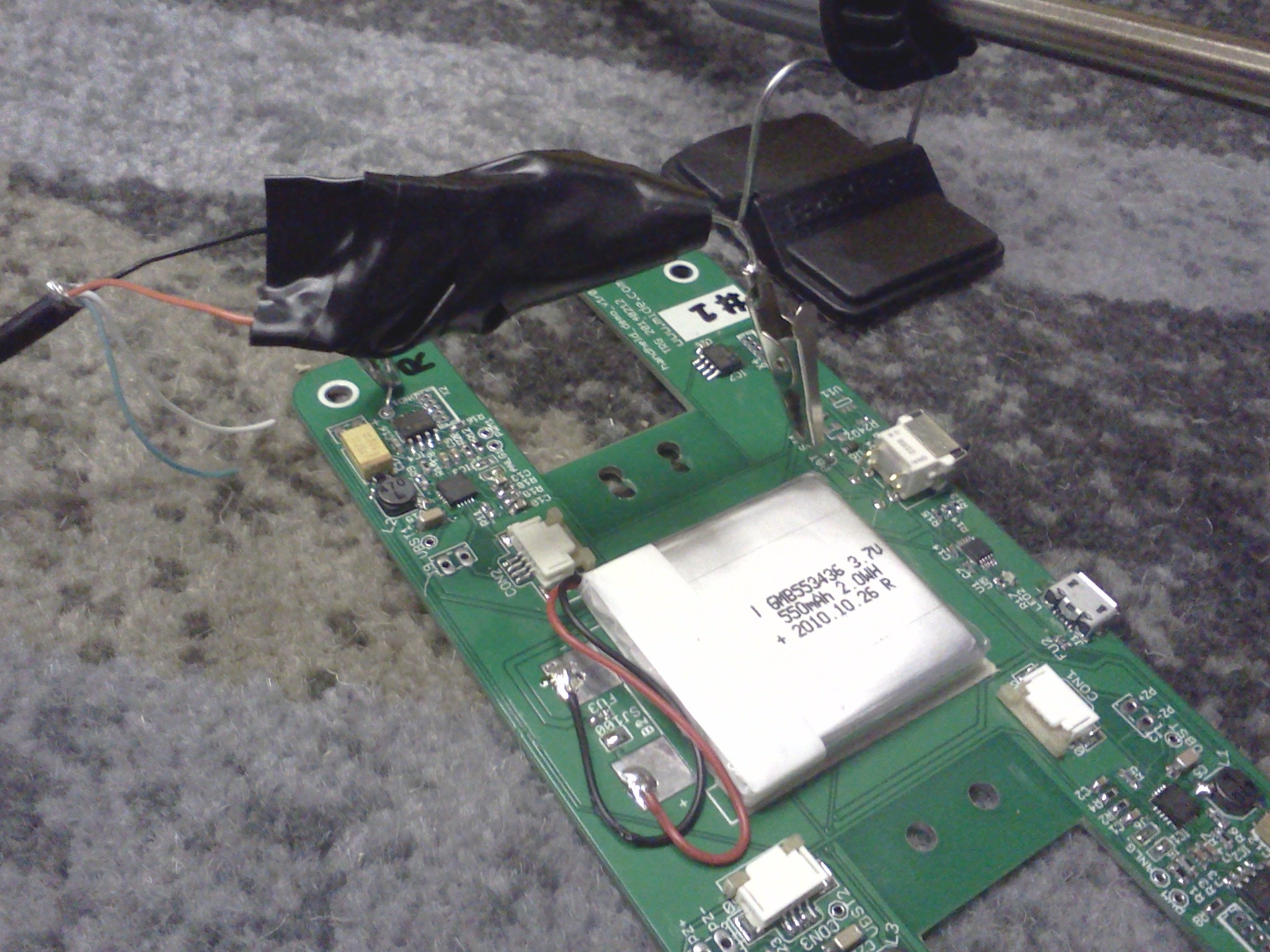
The replacement guts consist of a SHIVR actuator, photodetector, 3x AAA battery holder and a small driver board. The driver board consists of a TI DRV8662 piezo driver and a handful of supporting discretes. The DRV8662 functions as a voltage booster and amplifier, stepping up a 3V-5VDC input to 100V and driving a bipolar output in response to a low-voltage (0-3V or so) input signal. The photosensor and an LED were glued up inside the hole where the ball used to be, and the connection between the sensor and a 100k bias resistor was wired directly to the DRV8662 analog input. The actuator was stood off on a piece of scrap metal to match the height of the button. A mechanical stop feature on the underside of the mouse button was Dremeled a bit to give the actuated button a bit larger range of motion. Last but not least, the top shell was spraypainted black to slightly disguise its origins as an old Microsoft ballmouse from about the Soviet era.


The purple amplifier board was fabbed using OSH Park sometime prior (for experiments just such as this) and pretty much follows the application example in the DRV8662 datasheet, except for the DC modification as follows: Remove the DC blocking capacitors from the IN+/IN- pins, connect your input signal directly to IN+ and connect a midscale reference to IN-. For a typical 3.3V supply voltage and appropriate setting of the gain selects, a 10k/10k resistor divider between 3.3V and GND is just about right. Note that although the datasheet warns against continuous operation of the DRV8662 to avoid overheating, at such low frequencies it doesn’t so much as get warm to the touch. (Actually, I found it nearly impossible to get the evaluation kit into overtemperature even under continuous, harsh drive conditions.)

Slightly less-cheesy thumpin’ phablet
Another up-and-coming use for linear actuators lately is to provide inertial haptic effects in handheld gadgets. Most folks are familiar with the kind emanating from the weighted motors used in phones and game controllers, but these are fairly limited: they can only shake “all around” (not in a specified direction), the amplitude and frequency cannot be independently controlled (the only way to get more oomph is to spin it faster), and neither can the phasing of the actuator (let alone between multiple actuators) be controlled. Oh yeah, and the spin-up and spin-down times are on the order of 100-400ms depending on the size of the motor, so forget about any sharp, rapid-onset effects. For these reasons, folks are experimenting with linear actuators, which can provide much more precisely controlled sensations (a good example is the proposed Steam controller, which features two touchpads with a linear voicecoil driver under each.)
A fun thing about the piezo bimorphs is they are extremely lightweight (less than 0.5 grams) – so when adding mass at the end to make an inertial driver, it’s basically all payload: that mass isn’t fighting against the dead weight of magnets or metal shielding components. So I decided to make a demo resembling a big phat phablet*, which could be a flashy quadcore phone or some kind of aesthetically addled game controller. Or, you know, a rounded rectangle hogged out of a piece of Delrin. Hey, rounded corners! This demo featured two actuators, one on each side. I slapped a total of 10g tip mass on each, held in place by a stylin’ dab of epoxy.

For this demo I laid out a made-for-purpose PCB (not just carved up what I had already hanging around) and sent it off to Gold Phoenix. It arrived juuuust in time, but that’s another story. The board layout had a total of 3 copies of the same DRV8662 circuit, with a spot for a small PIC12 microcontroller at each to supply the waveforms. (The 3rd circuit was to be for a third, surface-bonded actuator, but I didn’t have time to implement it.) The program on each PIC consisted of a simple arbitrary wavetable generator (a handful of basic waveforms such as sine, square and directional “punch” were generated by a python script and slapped into lookup tables) and a series of calls to the waveform generator function with varying amplitudes, frequencies and waveform index to generate the demo effects. The waveform output itself was driven on a PWM pin and filtered to provide a proper analog input to the driver, and a GPIO pin was used for master-slave synchronization between the PICs.
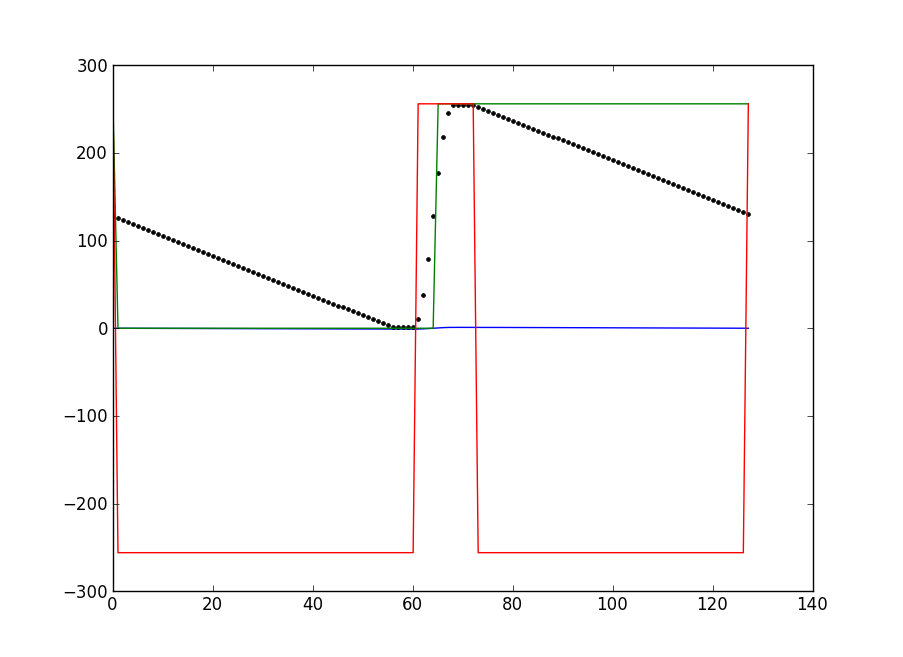
As before, the static deflection capability of the actuators was (ab)used to produce directional effects, such as making the device lunge toward or away from the user (fast drive stroke followed by a slower position-and-hold return stroke), or wiggle by driving them with out-of-phase square waves. With the 10g of mass, the usable frequency range was from about 30Hz to a few hundred Hz. Above 350Hz or so, the drivers reached their power limit and the output waveforms began to distort, producing significant audible noise in addition to motion. Qualitatively, this frequency range goes from a deep rumble to the sensation that there’s a very pissed-off mosquito trapped under your hand. You can’t feel it over the internet, but you can see the actuators throwing in the video below.
If this had been a real smartphone/etc. with a touchscreen, the actuation could respond to touch activity to produce effects like:
- Simulate surface texturing, i.e. give different screen areas different feels or make areas feel “pushed in” or “popped out”
- Simulate sticky and slippery spots on the screen by vibrating the screen at high frequencies to modify stiction
- Create the sensation of inertia or heaviness in the device, resisting as the user shakes or moves it around
- Create the feeling of compliance, i.e. make the rigid glass screen feel like rubber and bounce when touched
- Create the illusion of tackiness, where the screen gets pulled with the user’s finger as they let go, along with a vibratory kiss as it pulls free
Demo Code Details
This was for a day-job project, so I can’t provide the actual sourcecode… but can at least describe a bit of how it works.
The waveform generator is pretty straightforward, with one slight tweak to allow for arbitrary amplitude control. The actual waveform data is stored as raw data at a 256-word-aligned boundary. From the beginning of the table, the current entry is moved to the PWM register, followed by a waitloop for a timer overflow flag and then incrementing the table pointer. One call to the waveform output function outputs one complete cycle. The total duration of waveform output is controlled (at the next level up) by how many times this function is called in succession (i.e. how many complete cycles are output at the configured frequency).
The PIC’s 16-bit timer is used to control timing of waveform traversal. It is a little odd, providing a configurable prescale, postscale and period register (PR) setting. The pre/postscale divide the timer by (1:1, 1:4, 1:16) and (1:1 to 1:16) respectively. The PR configures the ‘top’ or rollover value to any value between 1 and 255. Between these settings, a wide variety of rates are possible. Once again, I used a python script (natch!) to build a lookup table which maps a frequency (2Hz increments) to the pre/post/PR combination which comes closest to it. With the on-chip 32MHz oscillator and 128-point wavetable, the realizable waveform frequencies are from 2Hz to somewhere upward of 1KHz.
Each wavetable entry stores one complete cycle of the waveform at 8-bit resolution, full amplitude (i.e. the waveform goes from 0 at its lowest point to 255 at its highest point; 128 is midscale). To achieve variable amplitude without storing scaled copies of the waveform or performing expensive math, some binary arithmetic is used. I describe the actual algorithm in this forum post. To avoid any audible clicking when switching waveforms, the tables are constructed so that the last point in each wavetable ends at midscale, and only multiples of complete wave cycles are output.
The sine, square and triangle waveforms are pretty straightforward. The ‘punch’ waveform consists of a very short quarter-sinewave drive stroke (from -fullscale to +fullscale) followed a linear ramp back to negative fullscale. As with the others, this waveform is time-shifted so that the midscale crossing of the ramp-down occurs at the last point in the table.

The Show
The first day consisted entirely of workshops, no exhibitions. Unfortunately our scheduling didn’t permit getting there early and seeing all of them, but did get to check out a couple. One of these was a sweet haptic texture rendering talk from researchers at UPenn. The math behind their approach will make your eyeballs spin backwards into their sockets a bit, but the results were incredibly realistic. On display were a tablet computer and stylus combo that faithfully recreated the sensation of drawing on sandpaper, cardboard and dozens of other textures on the slick glass surface, and the same algorithm implemented in a force-feedback arm for texturing 3D virtual surfaces. The algorithm and texture database are open source and published online.
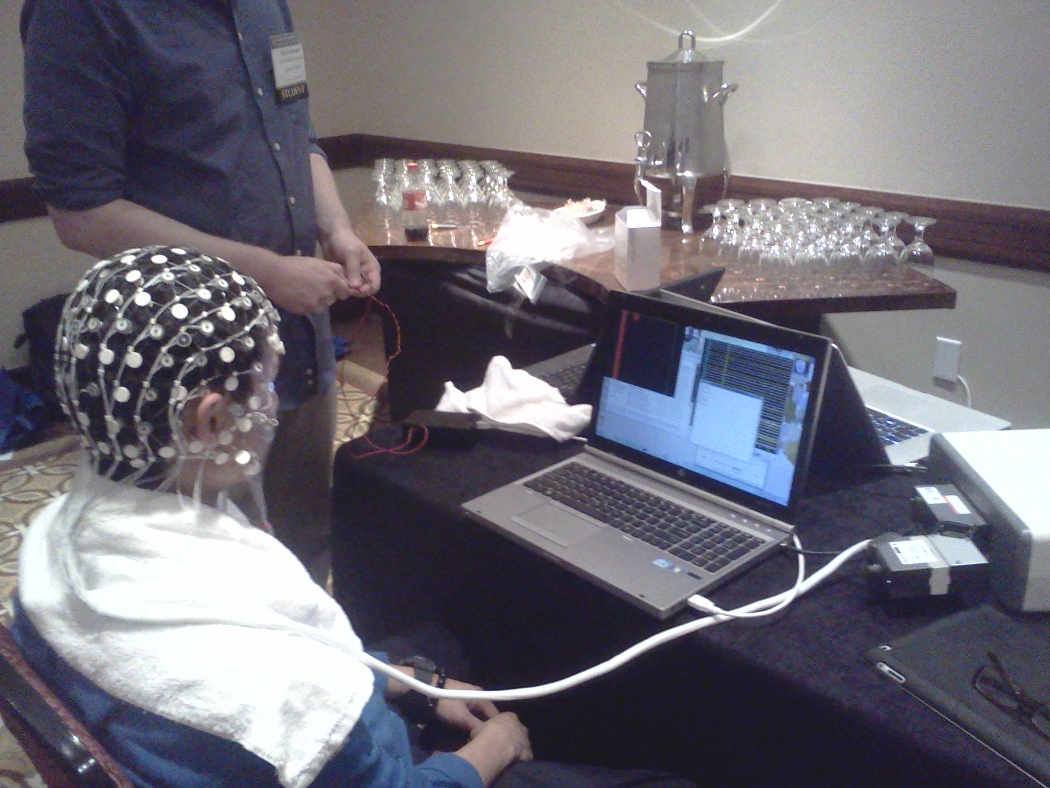
The other was probably the most badass-looking Brain-Computer Interface setup known to mankind. You think you’re cute with your little Emotiv headset and its 3 thumbtacks touching your mop? Yeah, this one has 128 saline-soaked electrodes for your mind-reading pleasure. You’ll look like a lunchlady wearing it, but everyone will know how ridiculous you think you look. Actually, the takeaway message I got from the BCI stuff on display was don’t believe the hype. The 128-node BCI demo was impressive in that a fresh-from-the-crowd individual could begin to steer a ball left or right onscreen by thinking (specifically, visualizing moving either their left or right arm) within about 10 minutes, without a lengthy training/calibration period. However, even with this very formal setup, those stories you hear about typing with your mind at normal speed, or guessing which picture you’re thinking about, etc… reality isn’t really there yet. (There is a character input scheme known as a P300 speller that does work, but it’s not nearly as straightforward as thinking about a letter and having it show up in your document. Input speeds are measured in characters per minute – not all that many – and require intense concentration.)
The next several days we were exhibiting. Unfortunately that meant we were stuck in our own booth, and couldn’t go check out the demo sessions. On the bright side, many of the demos were left set up between sessions, so we could at least sneak a peek around during e.g. poster sessions (when the exhibition section was a ghost town) and get some idea what they were about. Oh yeah, this is definitely a University-research-heavy conference, so Arduinos everywhere! In retrospect, probably not the ideal venue to try and hawk raw actuators to (nonexistent) smartphone-company scouts, but highly informative regardless.
That said, there were a few industry folks milling around. A few from names you might expect to see here, and even more from companies you’ve probably heard of, but would not expect to be interested in this stuff. Oh yeah, and a haptics show would not be complete without a scout from the notorious “I” company there. Not the rounded corners one, I mean the other “I” company, that seems to elicit groans from the entire haptics community. A guy from there walked up to our booth, so I tried to ask (ahem, tactfully) what exactly they did/sold, what value they added.
“So what do you guys do? Some kind of… software, right?”
“Oh yeah, there’s a software package… we champion the cause of haptics… and mainly, you know, licensing…”
He wasn’t carrying a clipboard or obvious spy camera, so at least there’s a chance we won’t find vague patents filed against everything in our booth appearing in exactly 18 months’ time.

Murphy Factor
No such trip is complete without at least something going wrong. In this case it was a problem with the handheld demo. I had built two boards as a precaution (baking on the leadless DRV8662s is fiddly enough, and there are multiple of them on the design – amazingly, both boards worked on the first try) and ordered a couple small LiPol battery samples. There was no time to charge them in the scramble to code the demo the night before, but no problem, we can just recharge this board with any USB cable, right? So the first morning of the show, I started one running and just left it out. After the first hour or so, it started to make an unhappy clicking sound and soon went silent. So I swapped in the 2nd board and plugged the dead 1st one in to charge. After a while, the 2nd board also started to go, so I switched the now-charged (harhar) first back in. Yyyyeah, not so much. It turns out (in later investigation back at the office) I had swapped two resistors during assembly, and the one that should have been standing in for a 10k thermistor was actually a 100k, causing the charger IC to think it was way out of a safe temperature range and shut down. (Hey, they’re all 0402 and completely unmarked; don’t judge.) Lunch involved a bolt to the nearest Radio Shack and MacGyvering a close-enough LiPol charger. Yeah, that’s a bundle of low-value resistors with their ends twisted together (to limit current to ~1C, or about 50mA for this battery), a rectifier diode to drop the 5V from a hacked-off USB cable down closer to 4.2V, and some alligator clips to strategic points on the board. The Shack’s cheapest/only multimeter was used to check the battery voltage periodically to avoid overcharging. Not exactly pretty, but it worked.

Dinosaurs!
Wait, what? Yes, actually dinosaurs. On the 2nd night there was a banquet held at the Houston Natural History Museum. So, dinner and drinks under the gaping maw of T. rex and a dozen of his closest dead friends. Pretty cool.

* Don’t you just love that word – the uneasy intersection of fat flabby phone and a phony wannabe tablet…
Leave a Reply