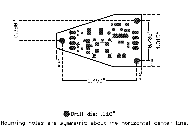
Board outer dimensions

Mounting hole detail
This information is common to all versions and can be found on the main Resources page.
USB cable connects to the fat end of the board, and motor attaches to the skinny end. Simple, eh? ;-)
The motor wires should be soldered to the two outermost pads at the bottom (narrow) end of the board. Polarity is unimportant. When soldering, take extreme care that the connections do not get bridged to neighboring pads (including the two innermost pads) or other adjacent metallic bits. Do not let stray solder flakes or balls adhere to the board or get underneath components. Most solder contains lead and possibly other unpleasant things (flux, etc.) -- wash hands thoroughly with soap and water after handling.
Important: There is a small solder bridge connecting the FETs together near the motor connection pads. This is intentional (however ugly it looks ;-) and not a cause for concern.


Drmn' Vibe firmware source code - PIC18F2x50 assembler relocated to 0x0200.
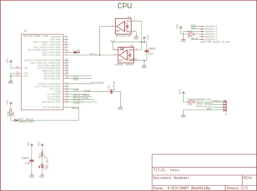
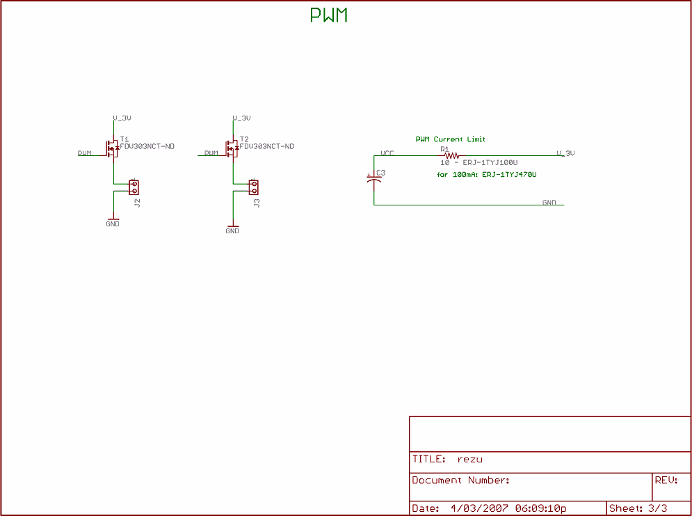
EAGLE schematic and printed circuit board design files


Back to the main Resource page
Back to the Trance Vibrator project page!
Email: drmn4ea @ that google-y moogley mail place