Optical mice work by pointing a tiny cheap camera at the surface of your desktop, tracking the motion of ‘interesting’ points in the surface texture (woodgrain, imperfections, highlight/shadow) as the mouse slides around over it, and converting this to an X and Y motion. An LED is used to light the surface beneath the sensor, typically at a very low angle to help highlight any surface roughness (so the sensor still works on rough, but solid-colored, surfaces such as paper). Many of these sensors allow you to read out the raw image, too. Historically, the sensors in optical mice have been a standalone chip with SPI interface, leaving a separate microcontroller to handle button clicks and PS/2 or USB interface – so you could hack a cheap optical mouse to output position or image data for unique scanner or robotics projects. Unfortunately, more and more of these high-volume, low-cost devices are moving to all-in one camera+micro+USB chips under an epoxy blob, so you can’t just buy any old optical mouse and expect any access to this internal data.
Videos:
Absolute microposition sensing using image recognition
Relative position sensing (i.e. just like a mouse) using the DELTA_X/DELTA_Y registers
Downloads:
Arduino Library
Naked mouse cam and lens wired to a microcontroller
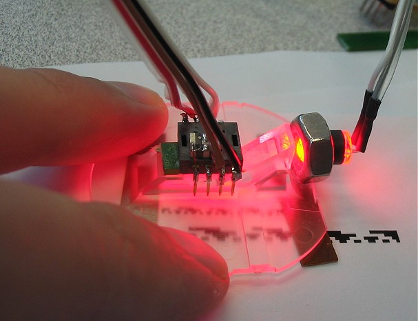
Fortunately, standalone SPI sensors are still alive and well. Mouser.com (no pun intended) sells some of these (Avago ADNS-2610 and ADNS-2620) for the exhorbitant price of $1.56 each. It’s a CAMERA for a buck fifty. Not exactly a *good* camera (grayscale, 18×18 resolution), but you can still do some neat tricks with it. Of course, you will still need a cheap optical mouse to steal the lens off of (or maybe an old CD player, etc.).
If you want to be all lame and boring, you could use this mouse camera as, well, a mouse. An onboard DSP is constantly watching the surface below as it slides by, giving you an up-to-date relative position (DELTA_X and DELTA_Y) just by reading a pair of registers. Each ‘delta’ reading contains the number of +/- pixels the mouse has moved in each direction since the last time you read it. Since you are only reading 2 registers, you can read this information at very high speed. There are some additional registers that will give you the max and min brightness, sum of all pixel values, and a ‘surface quality’ value that represents the number of trackable points (divided by 2) under the imager.
But if you want to dig deeper, a builtin diagnostic feature lets you bang some other registers and return the entire image under the camera. A few things worth mentioning before you go further, though: this IS meant as a diagnostic feature only; they sell these things as mice and not cameras after all, and this feature is not the best implemented. There are 324 pixels (18×18 array), but you can only grab one pixel per frame. So when you get the image, you are actually seeing pixels composited together from 324 separate frames across maybe 1/2 second. If the camera is moving during this time, you’ll get a garbled image, so if you have this puppy strapped to a robot to take pictures (or position the robot), your robot has to stop for pictures. Also, your maximum full-image rate is only a couple images per second.
Following are some demos of monochrome and color image acquisition, surface identification and micro-position sensing down to the um range.
Circuit:
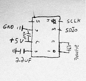
The ADNS-26xx parts only require a couple external components: an oscillator and a couple capacitors to stabilize its power supply and internal reference voltage. The oscillator frequency (about 20MHz-25MHz) is not critical; any cheap ceramic resonator will work fine here. So your complete parts list is:
1x ADNS-2620 mouse cam
1x 24MHz resonator (speed not critical)
1x 2.2uF capacitor
1x 0.1uF capacitor (optional but recommended power-supply bypass; value not critical)
Grabbing images:

The sensor’s great for reading that pesky fine print.
Above is a sample image taken from the sensor, looking at the little “Equal Housing Lender” glyph on some credit card junkmail. See below for some more. The process is straightforward; write once to the PIXEL_GRAB register to arm it, then read it 324 times (18*18) to read out the image bytes starting from the top left pixel. (Or use my Arduino library ;-)
And no, I’m certainly not the first to think of this. See here for a demonstration where someone combined the image and position readouts to use the mouse as a crude handheld scanner. I haven’t tried it, but I wonder how well this can see your fingerprints if the angle is right. (I assume not very well, otherwise mouse companies would have already enabled frame-grabbing on USB mice and tried to sell it as combination mouse and biometric ID thingy.)
Color imaging:
The grayscale sensor can be used as a crude color imager by replacing the standard red lighting with an RGB LED, and taking one frame with each color lit in turn. Depending on the LED, you may have to scale the R/G/B frame data differently for more accurate color representation. I assume like most photodiode technology the mouse cam pixels are most sensitive to the red-IR range, but the LED I used had a pretty weak red, so it was kind of a wash. (The image here is scaled red=0.75, green=1, blue=0.75).


2D position finding using the “Christopher Carter Algorithm”:
Very simple position-finding routine I wrote for testing purposes; named after a magician’s trick where the blindfolded practicioner (renowned hypnotist Christopher Carter, in the first case I saw it) “reads” a name written on a dry-erase board by swiping a finger across it at a few different heights. This is a similar idea, using a basic edge-detection to identify regions (“where to read”), then read them by the brightness at the center of each region.
In this method, you create a known optical pattern (in this example I used Gray Code) and apply it to the surface whose position you want to measure. Then aim the camera at it so that it looks at a small subset of the optical pattern at any given time. Ideally, each ‘pixel’ of the optical pattern should cover a 2×2 or more (3×3 or 4×4) pixel area on the sensor, since the optical pattern and the sensor’s pixels will never be *perfectly* aligned, and thus will blur across a couple neighboring pixels. Now you can identify the unique pixel pattern under the sensor and match it its position in the full optical pattern.
In a project at work, we needed to know how far a visual indicator pin on a piece of machinery was extended at any given time, and whether its position was in tolerance (reducing human observation error in dark and foul weather conditions). Since the sensor could not be permanently attached, we also wanted to be able to measure slop or shifting of the sensor itself relative to the pin, which would produce an incorrect reading. The small space, large pin travel and need for sensor cross-checking made common 1-D proximity sensors less attactive.
Definitions: The “pixel grid” is the actual sensor array. For ADNS-26xx, this is always 18×18. A “region” is one individual mark in the optical pattern, corresponding to a 3×3 (etc.) region of the pixel grid as mentioned above. The “region grid” is the array of these regions overlaid somewhere on the pixel grid. For example, with an 18×18 pixel grid and each region 3×3 pixels, the region grid overlaid onto the sensor can be as large as 6×6.
By performing this 2-stage lookup (find region grid offset on pixel grid, match region grid to known optical patterns), the total computation time is reduced by mainly working with only a small subset of the pixel data (the region grid), and the positioning resolution is at least (region size) and at most (pixel size). Working with only the center pixel of each region, to the extent possible (rather than e.g. averaging the entire region’s pixel values), is also beneficial since the regions may not be perfectly aligned to pixels and the focal plane at close range is very narrow (<1mm), thus the image may not be completely in focus – especially if looking at a curved or otherwise 3D surface. So all the pixels toward the edges of the region will tend to dilute the reading.
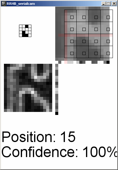
Absolute 2D position encoding/decoding using a Gray Code pattern. Position is resolvable generally to 1 pixel, in this case measured at about 2.4 mils (about 70um). The top-right shows the raw image with region grid (black squares) overlaid aligned to the strongest edges (pink crosshairs). The bottom-left shows the edge-detection itself, and finally, the top-left shows the recovered optical pattern. The actual position is the index of this pattern in the known fullsize pattern + the region grid’s offset.
Assuming an 18×18 image sensor:
Perform edge detection by taking the derivative of the image. Embedded systems such as Arduino are barely suited for non-integer math, let alone calculus, but we can take a poor-man’s “discrete derivative” easily by just subtracting neighboring pixels. Neighboring pixels on a uniform surface will not differ by much, so subtracting two neighbors will yield a low number, while along an edge, one will be very different from the other. We want to figure the vertical and horizontal edges separately. And we don’t care about the exact location of ALL the edges per se, just want to know on which rows and columns they occur. Once at least one good, strong edge is detected in each direction (horizontal and vertical), we know where to align the region grid so it is centered on valid regions.
For each horizontal row: For each pixel, its edginess (likeliness of being along a *vertical* edge) is given by the absolute value of (pixel – left neighbor) + the absolute value of (pixel – right neighbor).
v_edginess[row][col] = int(abs(image[row][col] – image[row][col-1]) + abs(image[row][col] – image[row][col+1]));
And of course that entire row’s vertical edginess is the sum of the edginess of all pixels in the row.
For each vertical column: Same thing, only going by columns, taking the pixel directly above and below. Again, the column’s edginess is the sum of the edginess of all the pixels in the column.
Obviously, the leftmost pixels has no left neighbors, and the rightmost pixels has no right neighbors (same goes for the top and bottom rows, they are missing neighbors on one side), so the easiest approach is to exclude them from the loops, e.g. for the 18×18 array, valid results start at (1,1) and end at (17,17). The result is an ‘edginess’ array of 16×16 pixels.
Once the region grid is positioned, threshold the region centers to black/white, then take the resulting region grid (4×4 in this example) and slide it around on an array containing the ‘known’ pattern until the best match is found. Obviously, in a real-world system subject to bad lighting, specks of dust, misalignment or misfocus, the match will not always be perfect. You might also want to know how well you can trust the measurement, so I compute a confidence value too. The confidence value is a function of the absolute % of regions matched, and the difference between the best match and the next best match. For example, if two different positions matched equally well (even if they are both “pretty good” percentage wise), you can’t uniquely identify a position and so your confidence must be zero.
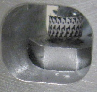
Another thing briefly tested was to place an LED behind the pin and observe its side profile (Alfred Hitchcock Algorithm?), which worked surprisingly well.

Side profile of the pin showing the lower part of the indicator groove.
Leave a Reply