Fun with 3D Printing: Print a Parametric Peristaltic Pump

So, I’ve been playing around with the Lulzbot we got at work. Inspired by emmett’s sweet planetary gear bearing design, I adapted the design to be not a bearing but a peristaltic pump. Like the original bearing design, the pump prints as a single piece – no assembly required! – with captive rollers and no rotary bearing/wear surfaces. The only extra part needed is a length of surgical tubing to thread through the mechanism. This initial print is a proof-of-concept and is driven by a standard 1/4″(?) hex nut driver or Allen key: for a real application, you’d want to add a mount for an electric motor or similar. This one (or one like it) will probably end up attached to a small gearmotor and solar panel in my greenhouse to slowly trickle water through an aquaponics tower.
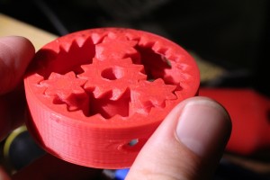
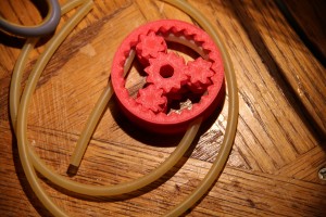
Printable Peristaltic Pump with captive rollers and minimal wear surfaces
Pump with latex surgical tubing installed

The pump design is written in OpenSCAD and pretty much fully parametric: the desired diameter, height, tubing geometry and a few other parameters can be tweaked as needed. There are a couple warts I’ll discuss later on.

Download:
You can download the OpenSCAD file here.

Video:
Here is a video of the pump in operation.

General:
Peristaltic pumps operate on the same principle as your esophagus and intestines (yes, really – yuck…) – a squishy length of hose is squeezed starting from one end and ending at the other, forcing any contents along for the ride. This type of pump has several properties that make it useful in certain applications:

  • Self-priming – can pump air or fluid reasonably well
  • Able to pump viscous, chunky or otherwise particulate-filled liquids that would gum up or damage an impeller pump
  • Gives great head – Ehhem… “head” refers to the maximum height the pump can push fluid. For a comparable energy input, a peristaltic pump can generally push fluid up much larger elevation gains than typical impeller types. Flowrate is another story of course.
  • Precise volume delivery – the amount of fluid (or air, etc.) dispensed per rotation of the motor is much more predictable than with an impeller pump. Using a servo or stepper motor, the volume pumped can be very accurately controlled. For this reason, peristaltic pumps are commonly used in medical equipment to meter out IV fluids, handle body fluids or dispense drugs.
  • Corrosion-free, isolated fluid path – Also of great relevance to medical applications, the fluid makes contact only with the tubing, making it very self-contained and minimizing the risk of contamination – e.g. all the nooks and crannies where foreign matter and bacteria could hide in other pumps. Very important when pumping bodily fluids out of someone and then back in (e.g. dialysis). Likewise, if your pump guts were metal, pumping corrosive fluids would be OK at the two never touch.

I really can’t stress the medical angle enough: in a hospital setting, peristaltic pumps are everywhere. Being able to print them off for practically free is huge.

Of course they are not without drawbacks; among them are fairly low flowrates, often “spurty” output, added friction losses and finite tubing life.

Assembly:
The pump prints out pretty much preassembled, but you still have to supply the tubing. Latex or Tygon surgical tubing is ideal, but most any pliable tubing (PVC fishpump tubing, etc.) can be used. To install, poke the tubing into one of the holes on the side of the mechanism (move the rollers if necessary so it is not blocked), pull through the desired amount of slack, then slowly advance the rollers to push the tubing up against the inner wall. When it reaches the other hole, push through and pull out any remaining slack. Note, the design is symmetric, so the concept of “inlet” and “outlet” port just depends on which direction you turn the rollers.

Design Considerations:

The diameter and wall thickness of the tubing dictate the pump geometry to some degree: the rollers and corresponding track must be wide enough to accommodate the tubing’s width when squished flat, and the clearance between the two must be enough to squeeze it flat without applying excessive force. This can be adjusted via the tubing_squish_ratio variable. The pump shown used a value of 0.5 with good results, but if you don’t need excessive pressure/head, lower values should work fine and reduce friction.

In general, a larger overall pump diameter will minimize wear on the tubing.

When using an FDM (plastic-extruding) printer, crazy overhangs in the geometry can’t be printed without support material (which defeats the purpose of a print-n-play design). The parameter allowed_overhang controls the level of overhang in the output based on what your printer can print, between 0 (no overhang whatsoever) and 1 (“infinite”, i.e. 90-degree overhang). Of course a ‘0’ setting is not very practical. 45-60 degree overhang should be OK for most FDM printers (I used a raw value of 0.75 for this one).

Warts / Future Improvements:

In the current version, the final OD will actually be slightly larger than the value you enter (specifically, by the calculated tubing squished thickness. This is a result of laziness on my part; keep this in mind or fix it if you need a very exact OD on the outer ring.

When operating at high speed, I’ve noticed the tubing sometimes has a tendency to slowly “walk” in the direction opposite of travel, being slowly pulled through the pump. A compression / baffle feature at the inlet and outlet would help prevent this by friction-locking the tubing in place. Alternately, it could probably just be fixed in place with a bit of glue.


Posted

in

by

Tags:

Comments

26 responses to “Fun with 3D Printing: Print a Parametric Peristaltic Pump”

  1. bart callens Avatar

    It doesn’t work for me.
    I’m using:
    – XP S3
    – Scad v.2013.01.22
    – Repetier-Host v.1.0.3
    – Slic3r 1.1.7
    (Copy from Thingiverse)

    I’ve problems with the exported scad-model to .stl,
    or even with the variant .stl-files found on Thingiverse…
    Importing in RH looks ok, but after slicing the center gear is replaced by its axis (the negative of the hexa)

    the design looks great!
    but I would like to see it work

    somebody?

  2. Tim Avatar

    It worked for me; proof is above :-)

    If you modified any parameters (or used the Customize option for the copy hosted on Thingiverse), try slicing again with the original file to start with and see if this works. While the parametric stuff ‘should’ work, it’s not exhaustively tested and some combinations of values could create impossible geometry.

    Note that if viewing the raw layers, the first layer may look bizarre due to any brims/etc. added by the slicer to help it stick.

    The toolchain I used is openscad (stl export) -> slic3r -> pronterface. I’m on travel right now, but when I get back I’ll see what version of each tool I used.

  3. J Avatar
    J

    This was an early Beta design, and the better version was going to be free too.

    However, whether this design clone release was coincidence or malice is irrelevant… as you just got somebody fired today.
    Karma -10

  4. Glenn Walters Avatar
    Glenn Walters

    Nice work! Commercial peristaltic pumps handle tubing creep in two ways – either of which could be implemented in your design.
    1. Let it creep! If the clearance is right, then the small amount of creep offsets the tubing wear. Just include an extra 6 to 18″ of slack in the pump tube upstream of the pump.
    2. Design clamps or retainers into the pump housing. Most commonly these take the form of pass-through hose barb unions (http://amzn.com/B00K26WHT4 )that secure into notches in the pump housing.

  5. Tim Avatar

    @J: Not sure what you are on about. Care to elaborate?

  6. Tim Avatar

    @Glenn: Good idea with the hose barb retainer approach. I’ve also seen an approach that is just a track with a wiggle or two in it that the tubing slots into, providing enough friction to hold it in place without compressing it too much (e.g. http://en.wikipedia.org/wiki/Peristaltic_pump#mediaviewer/File:Peristaltic_pump_LAMBDA_PRECIFLOW_-_pumping_mechanism.gif)

  7. J Avatar
    J

    @Tim
    The design used that hexagonal hole to lock pieces together, and the tube hole diameter was meant for 5mm OD food safe silicone tubing. I can’t prove whether you came up with this yourself, but our company has a zero tolerance policy for leaks. The chances your exact gear tooth count would randomly match ours is almost zero. Also, the early design (for all intensive purposes “your design” now) had a problem, and will slowly push the tubing out of the device. The reason this happens is “your” mandrel roller is of a slightly larger diameter than the gear tooth, and thus has a slightly larger arc length than the gear diameter. You can fix “your design” by slightly reducing the roller size to the gear diameter. I made the same mistake, and it took around 3 iterations to fix.

    I don’t have time for people who talk with their friends on facebook about projects they know little to nothing about. However, there are real-world consequences for employees that may try to rip off the CEO. i.e. the person who wasted $14k dollars worth of time/labor costs is being fired, and should be thankful I’m not suing due to a lack of proof.

    It is disappointing to see a half done design float into the public arena, but it is true that we planned to give the design away given we saw no commercial value in this product as it can only practically be 3D printed.

    Best of luck,

  8. Tim Avatar

    @J: I can assure you my design is not “stolen” from any random company, but is a minor adaptation of Emmett Lalish’s well-known Planetary Gear Bearing design from Thingiverse (linked above: http://www.thingiverse.com/thing:53451), published on 2/23/2013. The number of sun and planet gear teeth is unchanged from Emmett’s original. You can easily download both files and compare them to confirm all of this (OpenSCAD files are plain text). My “design” involves nothing more than adding/intersecting a few cylinders here and there, and cleaning up the resulting overhangs.

    A sidenote: It’s unfortunate that you burned through $14k designing something similar, but I’m honestly not sure how. I’m not a mechanical designer by any stretch (my day-job is as an electronics engineer), and put this together over the course of a few nights here & there after the wife & baby were asleep. As for being fired (you or your employee; I’m not clear on which) over similarity to a design that wasn’t commercially viable and was supposedly going to be released for free anyway, that smells pretty fishy – maybe something to take up with the EEOC (or possibly a therapist).

    PS: I’m pretty certain we don’t work at the same company. I had a beer with the CEO of mine after hours yesterday (Monday); both of us are still very much employed. Anyway, all the Mechies where I work have full Solidworks seats and I can’t get them to touch OpenSCAD with a ten-foot pole, despite much proselytizing :-)

  9. J Avatar
    J

    Fishy or not, we take our NDA legal agreements seriously. The whole project has been halted as I absolutely refuse to pay staff or sponsor nonviable designs.

    If you won’t publish our STLs, than please fix your design mistake so other people can at least use the design properly.

    I am glad you work for a nice company, and have a good reputation with your employer. Ask your CEO what he/she would do in the same situation, as actual project labor costs may surprise you.

  10. Tim Avatar

    @J: This is the beauty of open source. Anyone can freely download the design I’ve posted and make any improvements they like. If I don’t fix my mistakes* timely enough, chances are someone else will. By next month I will not be at all surprised to see derivatives of this design in square or other-shaped carriers, with mounts for various types of motors, with tube retention features, geometry tweaks to reduce creeping, gear reduction stages…

    You might want to google Direct Digital Manufacturing before dismissing designs as nonviable just because they can only be done additively. Anything you can do with FDM you can do with stereolithography, laser sintering or half a dozen other ways. DDM doesn’t make sense for everybody right now, but these machines are getting faster and cheaper all the time.

    Not sure how I would publish .STLs of your design, since I don’t have them (and for the avoidance of doubt, don’t want them). I had hoped I’d made that clear enough above. On that note though, some free advice. Since it’s clear this industrial espionage talk is foil-hat rubbish, if you really did fire an employee on such unsubstantiated grounds, you should probably run, not walk, to the nearest law firm and retain defense…

    * In this design, the roller vs. gear diameter are nominally equal; any difference comes from the user-adjustable tolerance parameters and resulting gear play. So I suspect a given user can make the tube creep backward, forward or not at all depending on the tolerance they select and how well their printer is calibrated. The creepage on my test print is extremely slight and can probably be fixed with a dab of glue, so most folks might not even bother with additional retention features.

  11. K Avatar

    Tim – really cool! I know zero about 3D printing, but need two peristaltic pump heads with different tubing sizes powered by a common shaft/motor. I’m environmental eng. working on prototype water treatment system. If I provide the details would you be interested in working up the revised openSCAD file? Would be willing to compensate you for your time.

  12. Mike Ackerman Avatar
    Mike Ackerman

    Hi there,

    Awesome idea. I’ve been wanting one of these for quite awhile. I’m curious… do you recall the cost of printing one of these devices?

  13. Daniel k Avatar
    Daniel k

    Great stuff. Roughly what flow rate are you getting out of this?

  14. Tim Avatar

    @bart: I printed this one with OpenSCAD 2014.03 and Slic3r 0.9.9. Rechecking on the version posted here, this setup rendered and sliced it without any apparent errors/warnings. Admittedly I didn’t try reprinting it though. Does your setup get at least that far?

  15. Tim Avatar

    @K: Sorry, pretty busy right now, but maybe someone else here or on HaD/Thingiverse can take you up on it?

  16. Tim Avatar

    @Mike: Neglecting any ‘soft’ costs (time, electricity), the print shown here comes in at 14 grams of ABS filament. The official Lulzbot filament is currently running ~$43USD/kg, so just a hair over 60 cents. The surgical tubing was about $1/ft on eBay.

  17. Tim Avatar

    @Daniel: I haven’t formally measured, but guesstimating from the video, 1 full rotation draws fluid about 4 inches (~10cm) up the tube with ID of 3/16 inch (.476cm). So maybe around 15cc per rotation. Flowrate isn’t really the strong suit of this type of pump though.

  18. blake Avatar
    blake

    I updated the code a bit to have a better surface for mounting (basically just added some flanges). I’m no expert in scad but if anyone wants the added lines of code let me know. Very cool though. thanks

  19. Stundo Avatar
    Stundo

    @J

    Hey J, I’m so glad you stopped in to clear things up. Just think what a horrible world this would be if we didn’t know you invented the Peristaltic Pump! Maybe you can take some comfort that Al Gore isn’t getting credit for inventing the internet either!

  20. […] getting access to a Lulzbot 3D printer, [Tim] designed a 3D printable peristaltic pump. The design was done in OpenSCAD, which makes it parametric and easy to […]

  21. Dave Avatar

    Hi Tim,

    We are pleased to inform you that your 3D Printed Parametric Peristaltic Pump has been featured at 3D Printing Industry News! The article can be found here:

    http://3dprintingindustrynews.com/creating-3d-printed-pump-planetary-gear-bearing/

    We thought our readers would love to hear all about your amazing innovation. We hope you are happy with the promotion of your blog and the images we have used.

    If you have any questions regarding the article, please do not hesitate to contact us at the listed email.

    Thank you,

    3D Printing Industry News Team

  22. MikeH Avatar
    MikeH

    Tim,
    Beautiful design! It fits my design needs very well and looks great. Now I just need to figure out why Slic3r insists on printing the negative space inside of the center hex hole instead of the gear around it. :)

    Mike

  23. MikeH Avatar
    MikeH

    And if anyone else had the same Slic3r issue, upgrading Slic3r from 1.0.0rc2 (yeah, I deserved what I got), to 1.1.7.

  24. Matt Kirk Avatar
    Matt Kirk

    Hey Tim, cool design! I printed one using your default settings and have been trying to get it work with vinyl aquarium air hose. Having difficulty getting good seal. Want to try surgical tubing as you suggest, but have to order online. What are the exact specs of your tubing? I read in comments that it has 3/16 ID, but what’s its OD? Thanks for any details!

  25. Martin Avatar

    Very nice little variation on the Gear Bearing. I could see this going a step further and pausing the print to place the silicone tube mid-print and avoid problems with feeding it through the wheels.

  26. mario Avatar
    mario

    Sareste così gentili da darmi direttamente un STL esattamente come da componente nei video?
    Non conosco il linguaggio openscad, ho provato a caricarlo ma mi da errore di sintassi in diverse parti.
    Grazie

Leave a Reply

Your email address will not be published. Required fields are marked *