Seiko Epson LCD model ECM-A0526, Interfacing
Bought this funky little panel for $11 on AllElectronics. John P has a very helpful timing diagram available for this LCD panel, along with pictures of his setup using a PIC microcontroller and DRAM module. Since I'm lazy cheap
a paragon of godlike infallibility, I decided that as long as I was just
building a quick little circuit on a breadboard to try it out with, I'd
forgo the memory entirely and just drive it directly from a
microcontroller for now. Eventually, I'll want some kind of crazy FPGA
contraption to blast an image at it from a SRAM at a fast framerate,
but let's worry about that later.
Setup:
A 12V* power supply, 7805 regulator, PIC18F4550 running with a 48MHz
oscillator, and a crude little negative-volts generator for the -17V or
so (contrast bias) the LCD needs, based around a LT1617 switching
converter chip. Last but not least, a MAX232 chip to load code (and
maybe, ultimately, the images/text...although this chip also has a
builtin USB transceiver) onto the microcontroller from a PC serial port.
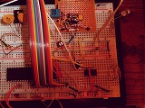
Click for fullsize
The LT1617 is visible as the little black speck in the middle of the
Veroboard at top right. I chose this chip because they're cheap as free
($2 direct, compared to $6.50 for MAX749 on Digikey...heck, that's half
the cost of the display itself) and Linear sent me samples. It's in a
5-pin SOT-23 package though; get your magnifying glass handy if you're
not used to working with surface-mount stuff. I found the four corner
pins will align nicely with the copper pads on the underside of the
Veroboard; once secured, you can bend the nuisance 5th pin (GND) up and
solder to it directly.
* Ghetto bench supply from spare parts. 12V when the brightness on the
backlight is turned way down, and considerably less than that when the
brightness is cranked and the backlight inverter is trying to draw half
an amp out of it.
Playing around:
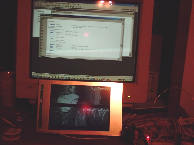
Displaying an image directly from the micro's code memory. (This is what happens when you let chicks dress you up.)

Click for fullsize
This chip only has 32KBytes of codespace (some of that's needed for
actual code ;-), but 640*480 pixels is 38400 bytes, which is why the
bottom of the top and bottom halves show as all black (reading from
non-existant memory addresses). Bottom and
middle, you say? Yep, that's a minor annoyance of this panel--in terms
of shoveling data at it, it's divided into two logical 'screens'...the
upper 4 bits of every byte write to one, and the lower 4 bits write to
the other. Sadly, even at 48MHz controlling it with a PIC directly is a
little slow (I pulled about 35fps here; there was still a bit of
noticeable flicker). PIC code and a crude little image conversion
script (*.raw to "DW H'xxxx' ", written in Perl) are in this zip
file...unfortunately, when wiring the LCD panel I think I flipped the
D[7..0] lines around backwards, and so unflipped them in software
rather than rewire the whole thing - if the results turn out funky for
you, comment out the appropriate lines in the conversion script.(sorry,
lazy...)
Click for fullsize
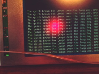
Besides the painful 32Kbyte codespace limitation, this chip has only
2048 bytes of RAM...To see how it would work as a text-only display
that could be updated in realtime, e.g. as a server process monitor, I
decided to map the screen as an 80x25 character display (each character
8px wide by 16px tall, with some space left over at the bottom of the
screen). That squeezes the memory requirements down to 2000 bytes to
store the ASCII character at every screen position, but since this
chip's driving the display directly, the characters have to be
generated in realtime for every frame...additionally, since half of
each byte out goes to the top screen and half to the bottom, you'd have
to keep switching back and forth between two different characters every
time a byte is written out (as you can see above, I didn't bother with
that for this little test). Even just blasting raw bytes to it to
display an image was borderline slow, all the overhead of creating
characters makes things unacceptably so: flicker central. So, the next
step will be to make up some kind of FPGA byte blaster / memory
controller :-) Luckily, an 8x16 font table is pretty small (4k), so you
could store several of them and select different fonts on the fly.
This zipfile contains the (ugly, nasty, ghetto) code for the test
above. Currently, it just repeats the first line (putting code to
re-index the data memory every line is just more instruction cycles I
didn't want to spend), and only for half of the screen (similar
excuse...see above). If I get around to making a proper memory
interface, I'll fix up this code and post the end result here. Or of
course, feel free to write your own :-)