Despite the impact of work, wedding planning and Super Metroid fan-hacks (not necessarily in that order ;-) on my freetime, my scheme to design a DIY-able open pick & place system is starting to come along. So far, there is a proper vacuum placement head, a rough idea of what the software architecture might look like, and this. For those who saw the last post, you probably guessed what it was leading up to.
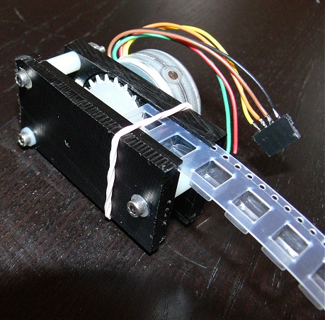
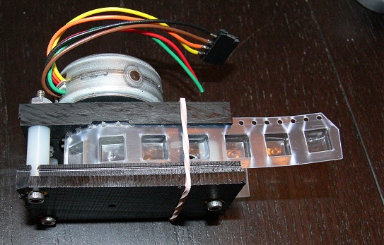
This is a simple proof-of-concept of a SMT tape-and-reel part feeder design. The main parts are a stepper motor and feed sprocket to advance the tape, two walls with guide slots, and a simple slider mechanism to allow the feeder to accept tapes of varying width. Please note that it does not (yet) include any mechanism for peeling and disposing of the tape covering. Suggestions and innovations in this area (as well as all others) are welcome!
All the parts were cut on a CNC mill – design files and G-code are available here. The .cb files included can be opened with the free version of CamBam. More photos / video and design details are available below.

The Tape Standard
The geometry of the standardized tape that holds SMT parts is documented in EIA-481-2-A, which until very recently was only available at a price too high for mortals (or from your favorite ‘alternative’ source, wink nudge). It appears that EIA disbanded at the end of 2010 and the documents are now public. Regardless, here are the parts of interest to us building a DIY tape-and-reel feeder:
Pitch (distance between sprocket holes): 4mm
Sprocket hole diameter: 1.5mm
Center of sprocket hole to edge of tape: 1.75mm
Center of sprocket hole to edge of component wells: min. 0.75mm??? (seemingly not specified; varies between manufacturers)
On opposite side of tape – ending edge of component wells to edge of tape: 0.6mm min.
Tape thickness: 0.2 ~ 0.4mm, not including covering.

The standard tape widths are 8/12/16/24/32/44/56 mm. For tapes 32mm and wider, a row of slightly elongated (same pitch) sprocket holes is added to the other side. According to various sources, the standard also says the pitch between part wells should be a multiple of 4mm and “Pin 1” (if any) should generally be on the sprocket side and facing forward. A longer explanation of the part orientation rules is that the part should be a) widthwise (its longer dimension, if any, across the tape); b) Pin 1 toward the round sprocket holes (unless this conflicts with the first rule); c) Pin 1 facing in the direction of travel (unless this conflicts with the first 2 rules). How religiously any given vendor adheres to these rules is anybody’s guess. There is also no rule saying the ‘well’ or pocket holding each part has to remotely match the size of the part (except to prevent it being able to flip over or rotate 90 degrees during shipping), so visual positioning correction is occasionally needed for parts from particularly lazy vendors.
Feeder Design Points
With these things in mind, the shown test-design uses the following dimensions, which seem to work well with varying size tape samples I fed through it:
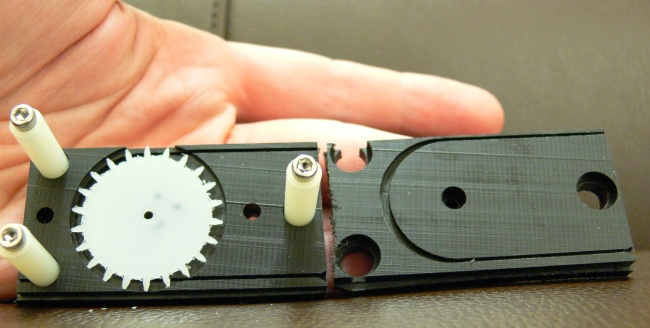
Sprocket thickness of 0.7874mm (.031″) – this is a ‘standard’ stock thickness in the US, so it was an easy first test. I sunk the sprocket so that it lies flush with the inside wall. With these values, the depth of the tape track is cut to 2.14376mm (0.0844 inches) to put the edge of the tape flush with the track when on the sprocket, forcing it to stay straight despite all the feed force being delivered on one side. For the ‘outside’ (non-driven side) wall, the track is cut to a depth of 1mm (0.039 inches). The width of the slot is 0.79375mm (0.03125″), as this is the closest (commonly available in the US) milling bit width that will accommodate both plastic and the slightly thicker paper tapes. To assist loading tape, a wider ‘mouth’ is cut on the input side of both sides’ slot, tapering to the slot width to guide the tape in. In reality, the mouth you see in the photos is not really large enough to be useful (it looked a lot bigger on my monitor!…). Also, the mouth on the non-drive side in the photos is on the wrong side since I completely forgot to account for this half being flipped over :p These are corrected in the downloadable files.
With the sprocket as designed, the tape track radius is 13.6mm (0.536″), and the track makes a 180 degree pass around the sprocket to eject the spent tape at the bottom of the same end it comes in on. In hand-testing some tape around the sprocket, I found it does not always sit flush against the sprocket throughout the entire 180 degrees, so the tape track is widened a bit around the sprocket to accommodate. The ~31mm sprocket diameter / number of teeth (22) was chosen purely for convenience on my part, as this is the tallest that would comfortably fit on the homebrew CNC mill I’m using for testing. In practice, a larger diameter is advisable so as not to limit the size of parts (deepness or length of the ‘wells’ vs. sprocket diameter and bend radius) that can be fed. Also, the reels themselves will be much taller than this anyway. Just keep in mind that as sprocket diameter goes up, so will the required motor torque to advance the sprocket one step, and the linear distance per step. At some point some form of gear reduction will be necessary vs. simply tacking the sprocket directly to the motor shaft.
To handle a wide (pun intended) variety of tape widths, a trio of smooth nylon PCB standoffs (0.250″ dia) are sunk and bolted into the drive side to act as sliding rails for the halves to be pulled apart to the desired width. A rubber band around both halves keeps them tensioned and in contact with the tape edges when loaded. This could definitely stand improvement, but it works for now.

Despite being a quick ‘n dirty test piece, the action of this feeder (by hand) is surprisingly smooth. The nylon spacers are pretty slippery, and the Delrin also provides a smooth, low-friction surface when machined. With the motor is a different story; these tin-can motors are 7.5deg/step and the driver board I’m using right now doesn’t really support microstepping low-current motors.

Leave a Reply